Electronic lock system

a technology of electronic locks and locks, applied in the direction of mechanical control devices, instruments, anti-theft devices, etc., can solve the problem of door creating an undesirable security risk

Inactive Publication Date: 2005-05-24
ONITY
View PDF16 Cites 53 Cited by
  • Summary
  • Abstract
  • Description
  • Claims
  • Application Information

AI Technical Summary

Benefits of technology

[0006]Another aspect of the present invention is directed to an electronic lock system for a door having an outside handle, an outside-facing surface, an inside handle, an inside-facing surface and a latch assembly. The electronic lock system comprises an electronic lock assembly and an electronic control assembly. The electronic lock assembly comprises a lock assembly housing, a first spindle assembly, a second spindle assembly, clutch assembly, a drive assembly, and a sensor assembly. The lock assembly housing is connectable to the inside-facing surface of the door. The assembly housing assembly comprises a base having a sidewall, a first plate spaced from and supported by the base, a second plate spaced from and supported by the first plate, and a cover spaced from the second plate and removably supported by the sidewall. The first spindle assembly is between the base and the first plate, the first spindle assembly connectable to the outside handle and to the latch assembly. The second spindle assembly is between the second plate and the cover. The second spindle assembly is connectable to the inside handle. The clutch assembly is between the first plate and the second plate. The clutch assembly connects the first spindle assembly to the second spindle assembly. The drive assembly is connected to the clutch assembly. The sensor assembly is adjacent the clutch assembly and has an output when actuated by the clutch assembly. The electronic control assembly comprises user interface and a controller in electrical communication with the user interface, the drive assembly, and the sensor assembly. The controller is configured to determine a condition of the clutch assembly based on the output of the sensor assembly.
[0007]The foregoing summary, as well as the following detailed description of preferred embodiments of the invention, will be better understood when read in conjunction with the appended drawings. For the purpose of illustrating the invention, there is shown in the drawings embodiments which are presently preferred. It should be understood, however, that the invention is not limited to the precise arrangements and instrumentalities shown.

Problems solved by technology

The location of the locking mechanism and the controller on the outside-facing surface of the door creates an undesirable security risk by being accessible for tampering.

Method used


Image

  • Electronic lock system
  • Electronic lock system
  • Electronic lock system

Examples


Embodiment Construction

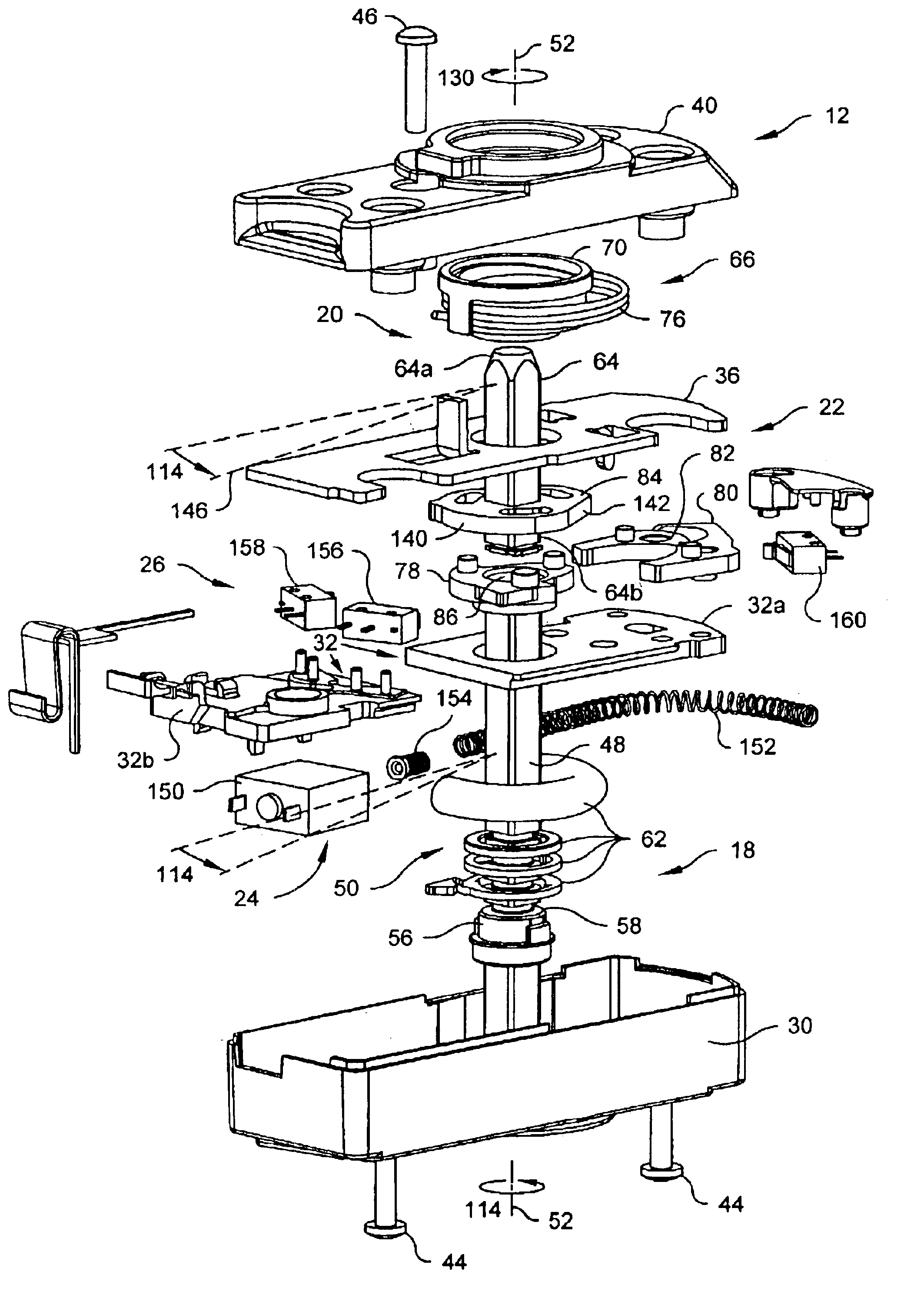
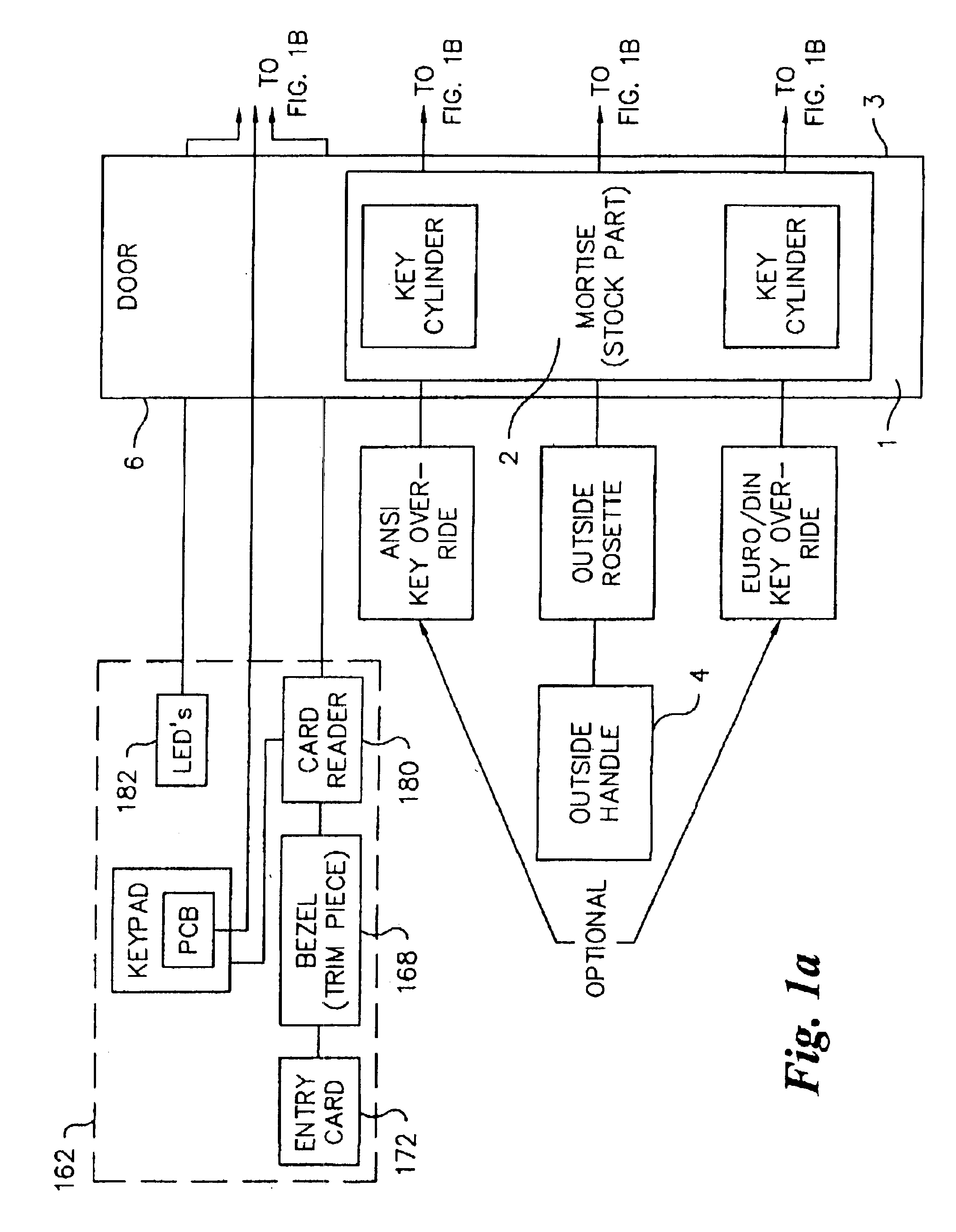
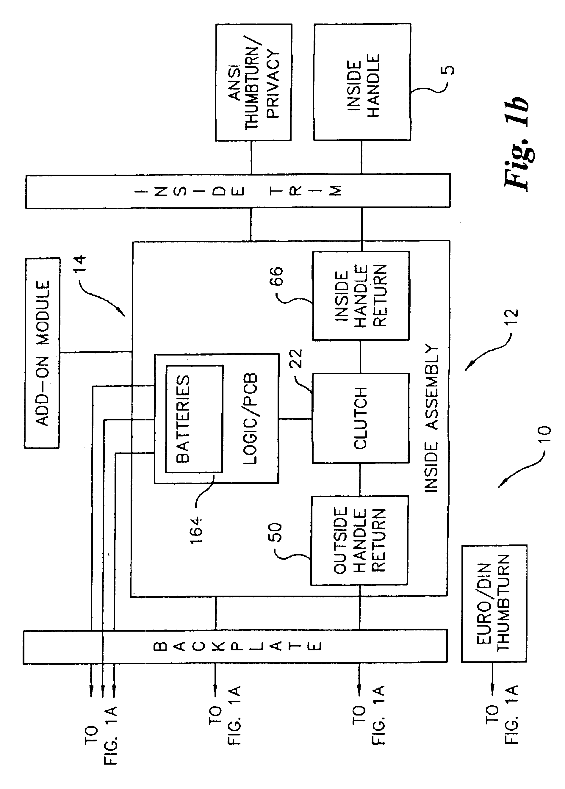
[0021]Referring to the drawings in detail, where like numerals indicate like elements throughout there is shown in FIGS. 1-11 a first preferred embodiment of the electronic lock system, generally designated 10, and hereinafter referred to as the “Lock System”10, in accordance with the present invention. Referring to FIG. 1, the Lock System 10 is for releasably securing a door 1 having a latch assembly 2 to a doorframe (not shown). The door 1 and latch assembly 2 can be any well known door and latch assembly, such as a door having a hinged edge pivotably attached to a doorframe and an opposite edge having a mortised recess in which a typical mortise lock assembly having a latch (not shown) that retractably projects beyond the edge of the door 1 and into an opening in an adjacent strike plate (not shown) in the doorframe. The Lock System 10 has an electronic lock assembly 12 and an electronic control assembly 14 (FIG. 1).

[0022]Referring to FIGS. 1-6, the electronic lock assembly has a...


PUM


Abstract

A clutch assembly for coupling a first spindle to a second spindle. The clutch assembly has a first disc connectable to the first spindle. A first finger is operatively coupled to the first disc and pivotable between a first engaged position and a first disengaged position. The first finger opposes rotation of the first disc in a first direction when the first finger is in the first engaged position. A second disc is connectable to the second spindle. The second disc pivots the first finger from the first engaged position to the first disengaged position when the second disc is rotated in the first direction through a first range of angular positions and rotates the first disk in the first direction when the second disc is rotated beyond the first range of angular positions.

Description

CROSS-REFERENCE TO RELATED APPLICATIONS[0001]This application is related to U.S. Provisional Patent Application No. 60 / 379,074, filed May 9, 2002, and claims the earlier filing date of the provisional application. Each of the above-identified related applications is incorporated herein by reference.BACKGROUND OF THE INVENTION[0002]The present invention relates generally to an electronic lock system. More particularly, the present invention relates to a door lock system in which an electronic lock assembly mountable on an inside-facing side of a door is connected to a mortise lock in the door and is actuatable by a user interface mounted on an outside-facing side of the door and in communication with an electronic controller mountable on the inside-facing side of the door.[0003]A typical mortise lock has a generally rectangular housing that is positioned in a mortised recess in an edge of a door that is opposite a hinged edge of the door rotatably attaching the door to a doorframe. T...

Claims


Application Information

Patent Timeline
Patent Type & Authority Patents(United States)
IPC IPC(8): E05B47/06G07C9/00E05B47/00
CPCE05B47/0669G07C9/00563G07C9/00658E05B47/0012E05B2047/0025Y10S70/59E05B2047/0031Y10T70/5438Y10T70/5677Y10T70/7062Y10T70/7079Y10T70/7102Y10T70/713Y10T70/8027
Inventor ALEXANDER, ARNONWEIMAN, ANDREWPAYNE, JONATHAN P.METIVIER, PASCAL GEORGES
Owner ONITY
Why Eureka
Try Eureka