Lighted battery cables

a technology of battery cables and jumper cables, applied in the direction of multi-conductor cable end pieces, coupling device connections, transportation and packaging, etc., can solve the problems of difficult to see the battery posts, potential hazards of devices, sparks, etc., to prevent ignition of explosive gases, easy retrofit the illumination system onto existing jumper cables, and selectively illuminate battery terminals or other objects

Inactive Publication Date: 2005-05-24
WORLD FACTORY
View PDF18 Cites 36 Cited by
  • Summary
  • Abstract
  • Description
  • Claims
  • Application Information

AI Technical Summary

Benefits of technology

[0011]This object is achieved by providing a battery cable assembly having a pair of electrical cables and at least one pair of clamps, each clamp being connected to one end of one of the cables for establishing electrical connection between the cables and electrical terminals of a battery. A light source is mounted on at least one of the clamps, the light source being powered by an electrical power source that is independent of the battery and located remote to the clamps. A switch, which is also located remote to the clamps, controls the flow of electricity from the electrical power source to the light source, allowing an operator to selectively activate the light source for illuminating objects near the corresponding clamp prior to or during connection to the battery.
[0012]The present invention provides significant advantages, including: (1) the ability to selectively illuminate battery terminals or other objects prior to connection of the battery cables to a battery; (2) the ability to locate the electrical power source for the light source and the switch for operating the light source away from the clamps, thereby preventing ignition of any explosive gases that may have accumulated near a battery; and (3) the ability to readily retrofit the illumination system onto existing jumper cables.

Problems solved by technology

As may be appreciated, these devices are potentially hazardous in the creation of sparks as the cables are connected or disconnected from the battery terminals.
Often, jumper cables must be connected when it is dark or otherwise poorly lighted.
Darkness makes it difficult to see the battery posts and ensure that the jumper cables' connectors are properly secured to the terminals.
Furthermore, it is very difficult to identify the polarity of the battery terminals and jumper cable connections in the dark.
However, explosive gases may accumulate near a booster battery or the battery to be charged, and opening or closing an electrical circuit using a switch on the clamp can cause a spark that may ignite these gases.
In addition, locating the electrical power source in the clamp may also lead to the creation of sparks if the batteries fit loosely within the clamp or otherwise break electrical contact during use.

Method used


Image

  • Lighted battery cables
  • Lighted battery cables
  • Lighted battery cables

Examples


Embodiment Construction

[0020]The present invention is directed to a lighted battery cable assembly, permitting the user to correctly attach the assembly to a battery in all lighting conditions.

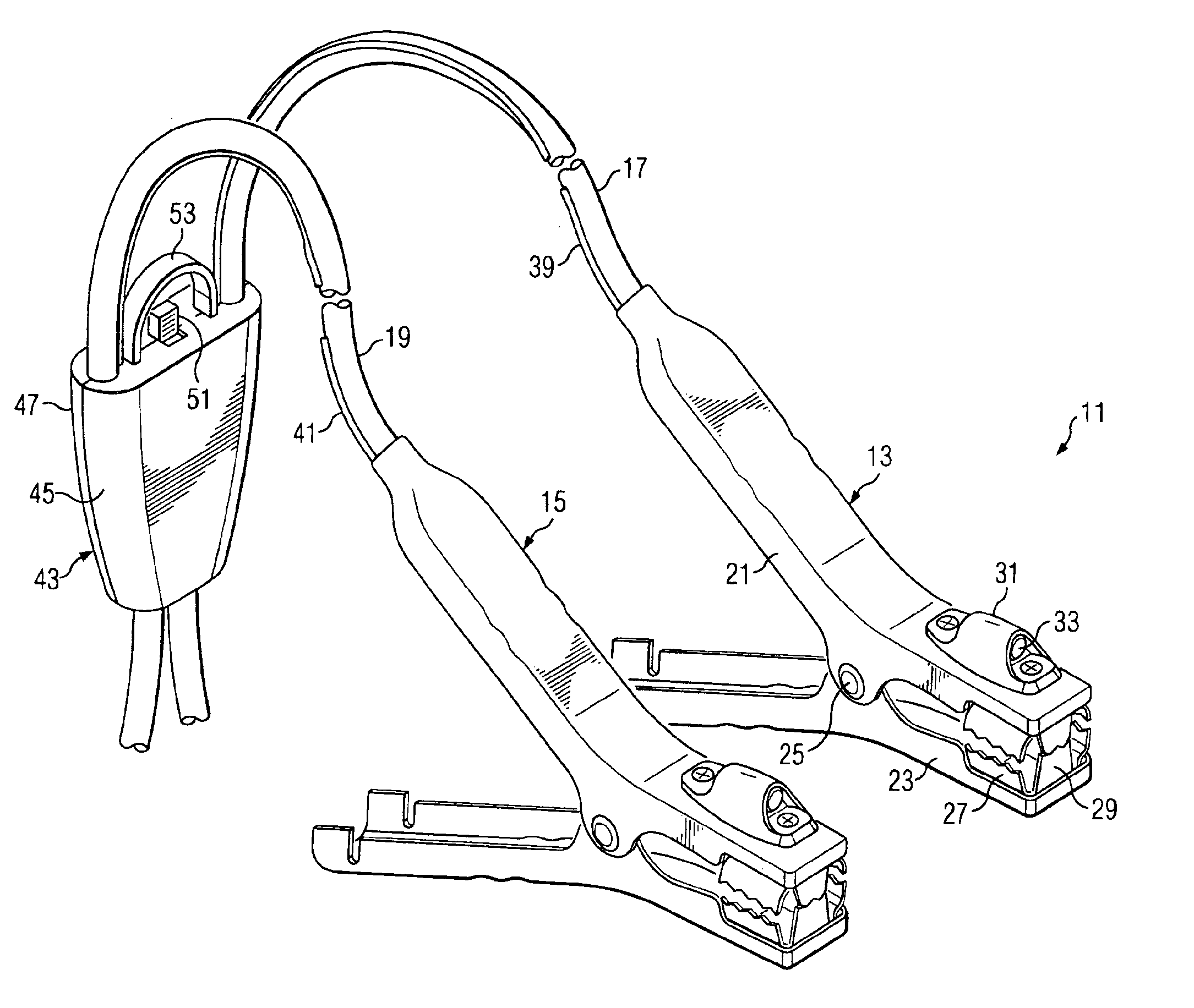
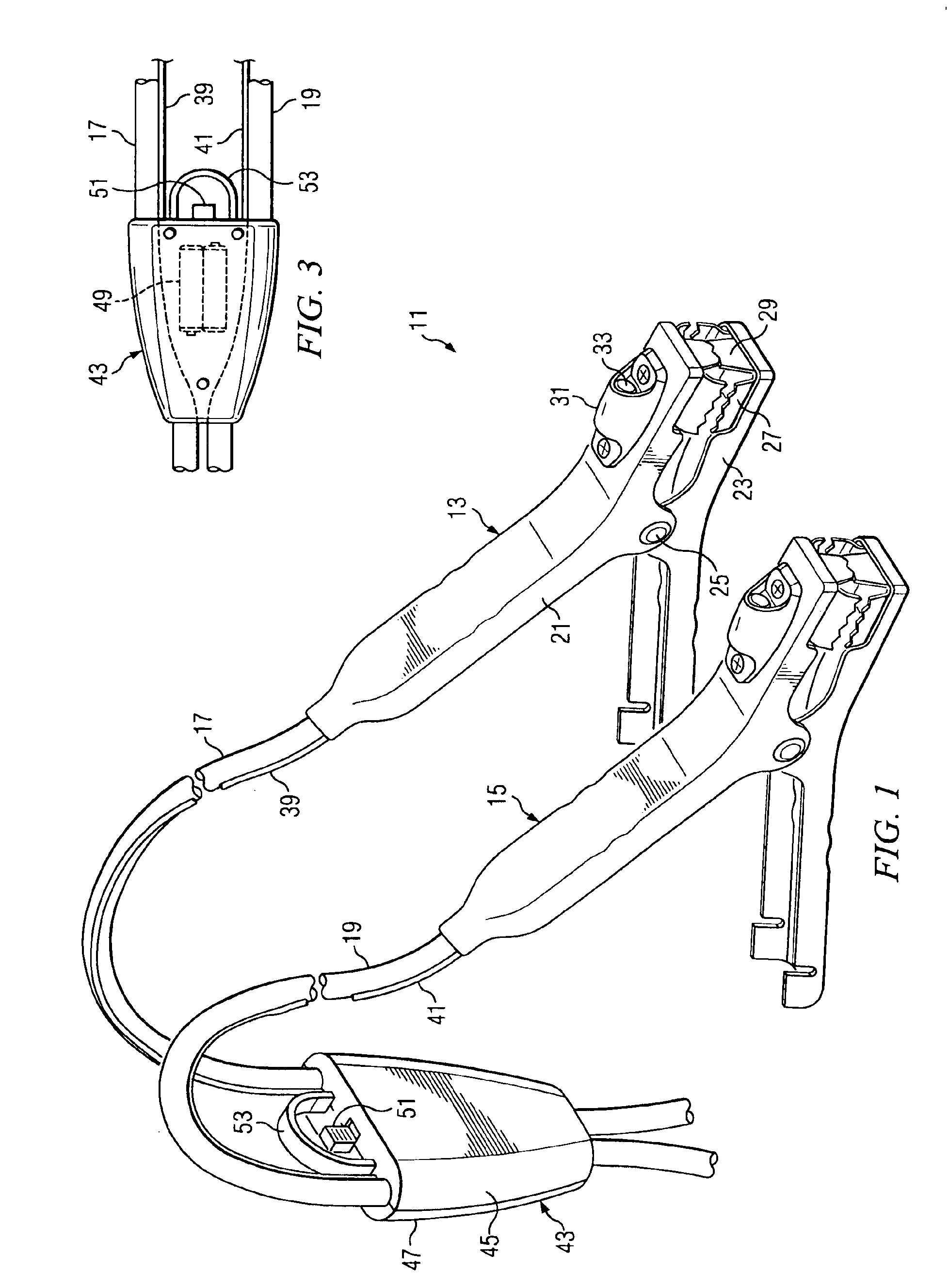
[0021]Referring now to FIG. 1, battery cable assembly 11 comprises two battery clamps 13, 15 for connecting insulated electrical cables 17, 19, respectively, to electrical terminals of a battery (not shown), such as the type of battery commonly used in an electrical system of an automobile. Clamps 13, 15 are shown as being identical, and it will be appreciated that the following description of clamp 13 also applies to clamp 15, though clamps 13, 15 may be dissimilar in other embodiments. Clamps 13, 15 are shown as clamps formed of pivoting sections, though clamps 13, 15 may also be of any type known in the art. For example, clamps 13, 15 may have portions that slide relative to each other.

[0022]Clamp 13 is formed from two clamp portions 21, 23, which are pivotally connected to each other by a fastener 25. Electrical...


PUM


Abstract

A battery cable assembly has a pair of electrical cables and at least one pair of clamps, each clamp being connected to one end of one of the cables for establishing electrical connection between the cables and electrical terminals of a battery. A light source is mounted on at least one of the clamps, the light source being powered by an electrical source that is independent of the battery and located remote to the clamps. A switch, which is located remote to the clamps, controls the flow of electricity from the electrical source to the light source, allowing an operator to selectively activate the light source for illuminating objects near the corresponding clamp prior to connection to the battery.

Description

BACKGROUND OF THE INVENTION[0001]1. Field of the Invention[0002]The present invention relates in general to the field of battery cables for connecting a power source to a discharged battery with clamps. In particular, the present invention relates to battery cables having a light source for illuminating objects near the clamps.[0003]2. Description of Related Art[0004]The use of battery cables is well known in the prior art. As may be appreciated, these devices are potentially hazardous in the creation of sparks as the cables are connected or disconnected from the battery terminals. Also, it is important that each cable is connected to the proper battery terminal to eliminate short circuiting the power source. Numerous attempts have been made to develop jumper cables having indicating systems that effectively indicate proper battery connection. Many of these types of systems utilize LED's, or other visual indicators, which illuminate when the cables are properly connected. U.S. Pat. ...

Claims


Application Information

Patent Timeline
Patent Type & Authority Patents(United States)
IPC IPC(8): H02J7/00H01R11/24H01R13/66H01R11/11H01R13/717H01R11/28
CPCH01R11/24H01R13/717H01R11/288H01R13/7177H01R13/7175
Inventor KUELBS, GREGORY G.PROBASCO, MAX A.
Owner WORLD FACTORY
Why Eureka
Try Eureka