Power line phase coupler system

a phase coupler and power line technology, applied in the direction of coupling device connection, electric controller, instruments, etc., can solve the problems of difficult to achieve reliable natural coupling, difficult to implement a reliable system, and difficult to achieve natural coupling. achieve the effect of increasing the overall communication efficiency of power line communication devices, simple, easy and convenien

Inactive Publication Date: 2005-05-24
ECHELON CORP
View PDF12 Cites 21 Cited by
  • Summary
  • Abstract
  • Description
  • Claims
  • Application Information

AI Technical Summary

Benefits of technology

[0026]A further object is to provide a power line phase coupler system that increases the overall communication efficiency of power line communication devices.
[0027]An additional object is to provide a power line phase coupler system that provides a simple, easy and convenient system to link the entire wiring of a building together for the purposes of providing a network for communication and control of devices electrically connected to the power line system of the building.

Problems solved by technology

However, consistent and reliable natural coupling is difficult to achieve and typically is not feasible for a reliable system to be implemented.
Natural coupling is especially difficult to achieve in larger buildings that have numerous electronic devices connected to power outlets within the building.
To provide adequate communications for the data signal between the two phases of the building, it is often times desirable to “couple” the phases together at the breaker panel.
Passive couplers do not enhance the data signal during bridging between the phases and many times a passive coupler will actually reduce the signal strength of the data signal.
Utilizing a passive coupler can be difficult since the capacitor may allow the lower power frequencies and other data signals to undesirably pass between the phases.
In addition, coupling the phases together at the breaker panel with a passive coupler can be difficult and dangerous even for skilled professionals.
Also, the signal strength of the data signal is weakened after passing through a passive coupler and sometimes cannot be detected by a receiver device.
In larger building structures a passive coupler simply is not acceptable to maintain the desirable signal strength of the receiver devices.
While these devices may be suitable for the particular purpose to which they address, they are not as suitable for repeating data signals between power line phases that can be easily installed by a user.
The main problem with passive couplers is that they are not suitable for usage within larger building structures or where numerous electrical devices are connected within.
The main problem with conventional repeater couplers is that they are designed to be utilized only within a main breaker panel and are not easy to utilize for most consumers.

Method used


Image

  • Power line phase coupler system
  • Power line phase coupler system
  • Power line phase coupler system

Examples


Embodiment Construction

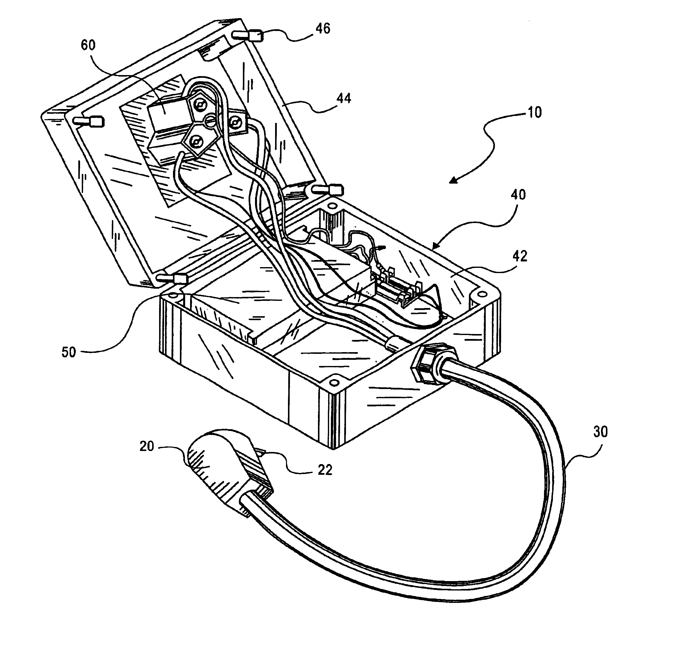
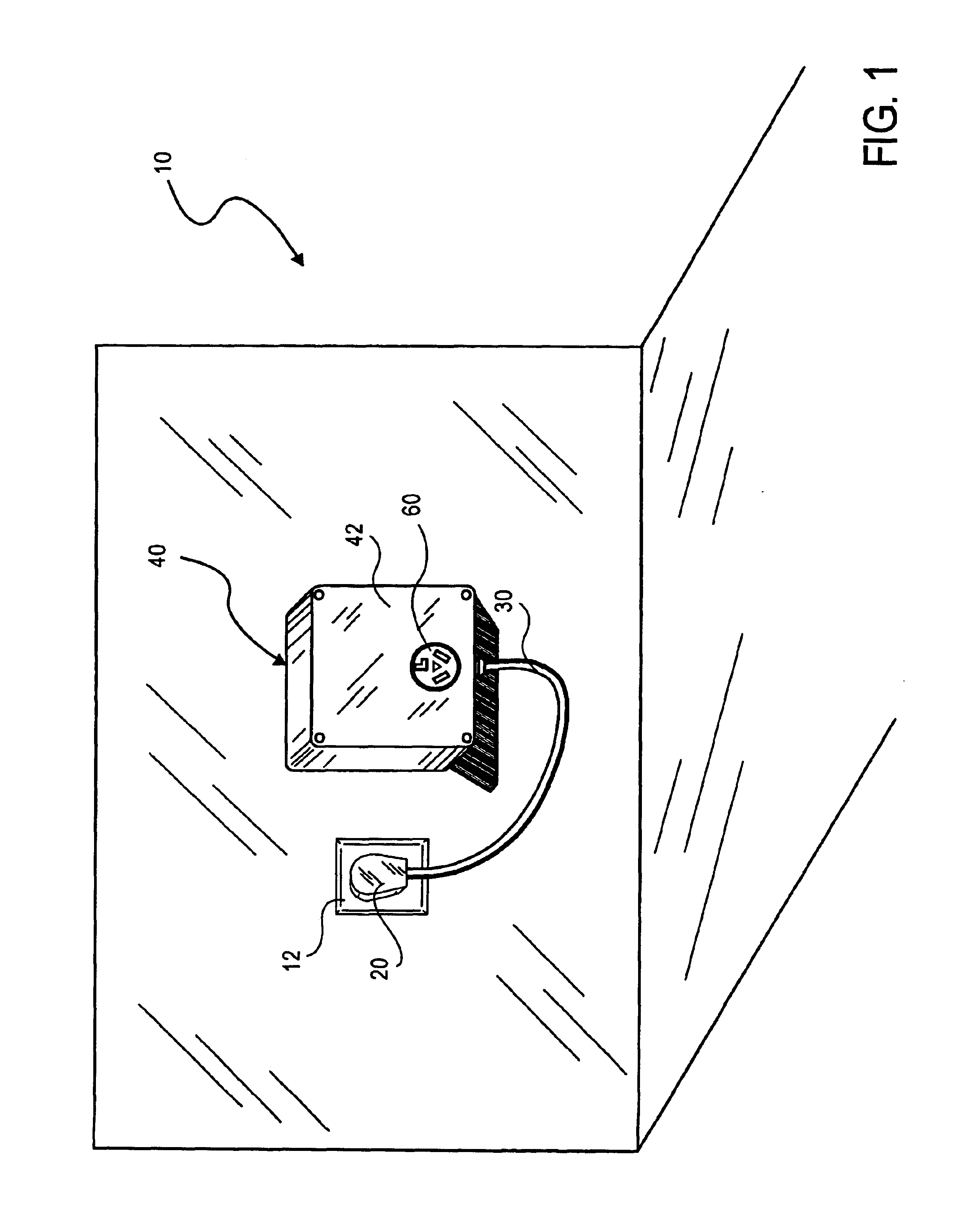
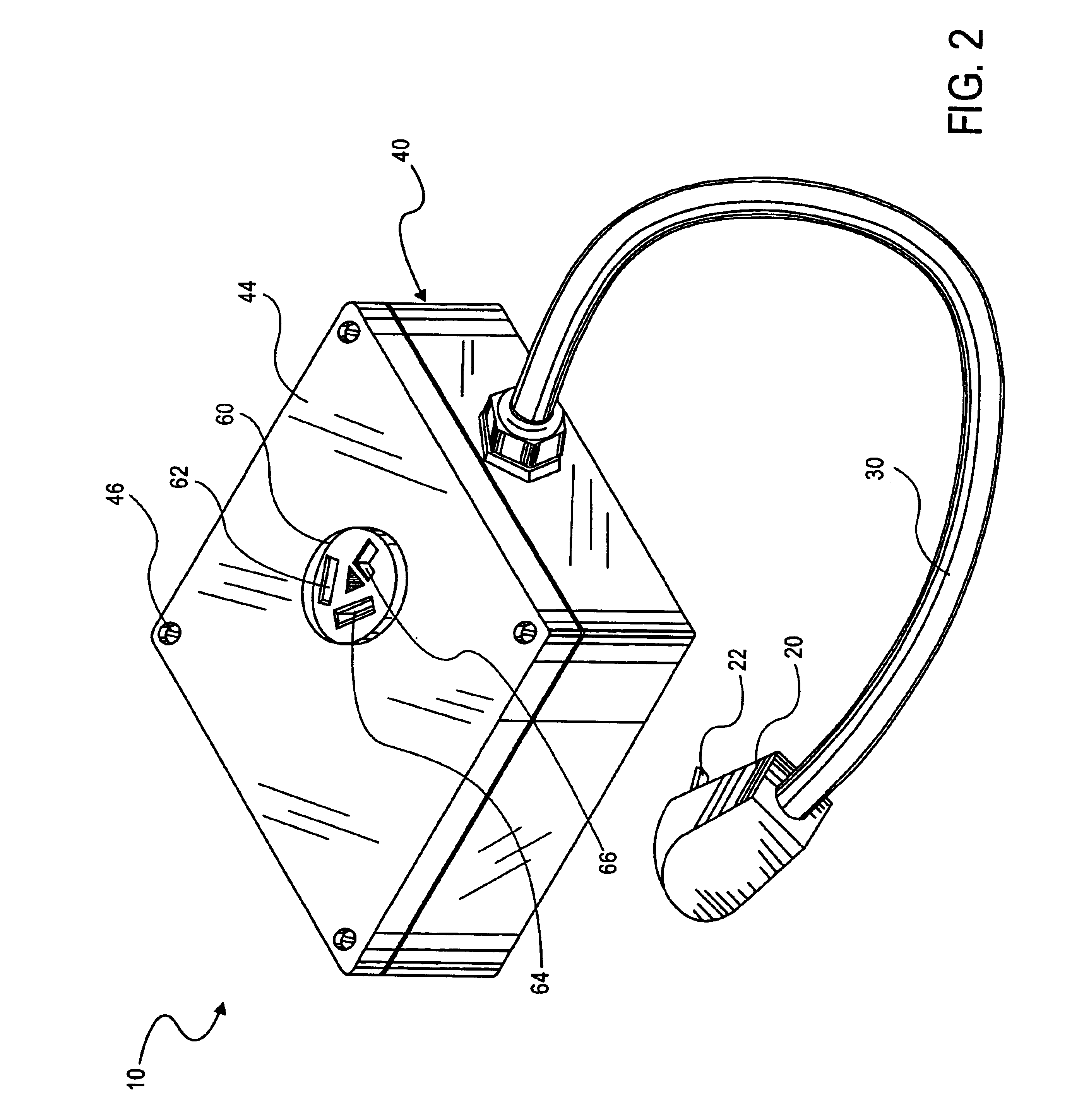
[0042]Turning now descriptively to the drawings, in which similar reference characters denote similar elements throughout the several views, FIGS. 1 through 11 illustrate a power line phase coupler system 10, which comprises a housing 40, a female connector 60 positioned within the housing 40, a male connector 20 electrically connected to the female connector 60 by a length of cord 30, and a repeater coupler 50 electrically connected to the male connector 20. The repeater coupler 50 is electrically connected between Phase A and Phase B of the male connector 20 for repeating and amplifying a data signal received from either phase to the opposite phase.

[0043]A conventional power line system of a building typically has a Phase A power line, Phase B power line and a neutral line wherein Phase A is 180 degrees out of phase with respect to Phase B. Some power line systems have a four line called the ground line. A conventional wall outlet 12 providing dual-phase power typically has three ...


PUM


Abstract

A power line phase coupler system for repeating data signals between power line phases that can be easily installed by a user. The power line phase coupler system includes a housing, a female connector positioned within the housing, a male connector electrically connected to the female connector by a length of cord, and a repeater coupler electrically connected to the male connector. The repeater coupler is electrically connected between Phase A and Phase B of the male connector for repeating and amplifying a data signal received from either phase to the opposite phase.

Description

BACKGROUND OF THE INVENTION[0001]1. Field of the Invention[0002]The present invention relates generally to power line phase couplers and more specifically it relates to a power line phase coupler system for repeating data signals between power line phases that can be easily installed by a user.[0003]Power line communication (PLC) is utilized to connect various electronic devices within a building structure via the electrical power system of the building. Networking of these electronic device may utilize two different but complementary PLC technologies: one for high speed data communication (computer networking, printer sharing, Internet connection, etc.) and one for control applications (designed for the lowest possible cost). Data communication applications have requirements that are completely different from control applications. Regardless of the PLC technology utilized, a home utilizing a multi-phase power line system creates several communication problems for the devices connec...

Claims


Application Information

Patent Timeline
Patent Type & Authority Patents(United States)
IPC IPC(8): H04B3/54H04B3/58H01R13/66
CPCH04B3/58H01R13/665
Inventor HAUCK, DOUGLAS L.KVIDT, DAVID L.JOHNSON, JEFF L.
Owner ECHELON CORP
Why Eureka
Try Eureka