Method and plant for fabricating drip irrigation pipes

a technology of drip irrigation and pipe, which is applied in the direction of tubular objects, coatings, domestic applications, etc., can solve the problems of obstructed or hindered extrusion pipe advance, damage to softened wall of conduit,

Inactive Publication Date: 2005-05-24
GIUFFRE CARMELO
View PDF8 Cites 40 Cited by
  • Summary
  • Abstract
  • Description
  • Claims
  • Application Information

AI Technical Summary

Benefits of technology

[0017]The invention has the object to provide a method for fabricating trickle irrigation pipes of the type described hereinbefore, allowing to obviate the drawbac

Problems solved by technology

This may lead to damage of the softened wall of the conduit.
Also in this case, the path along which the pipe and the dripping elements are submitted to mutual compression

Method used


Image

  • Method and plant for fabricating drip irrigation pipes
  • Method and plant for fabricating drip irrigation pipes
  • Method and plant for fabricating drip irrigation pipes

Examples


Embodiment Construction

[0062]Referring to the figures, it has to be pointed out that any characteristics appearing together in each of them may be individually combined to each other in order to obtain further obvious and possible combinations, not shown in the figures.

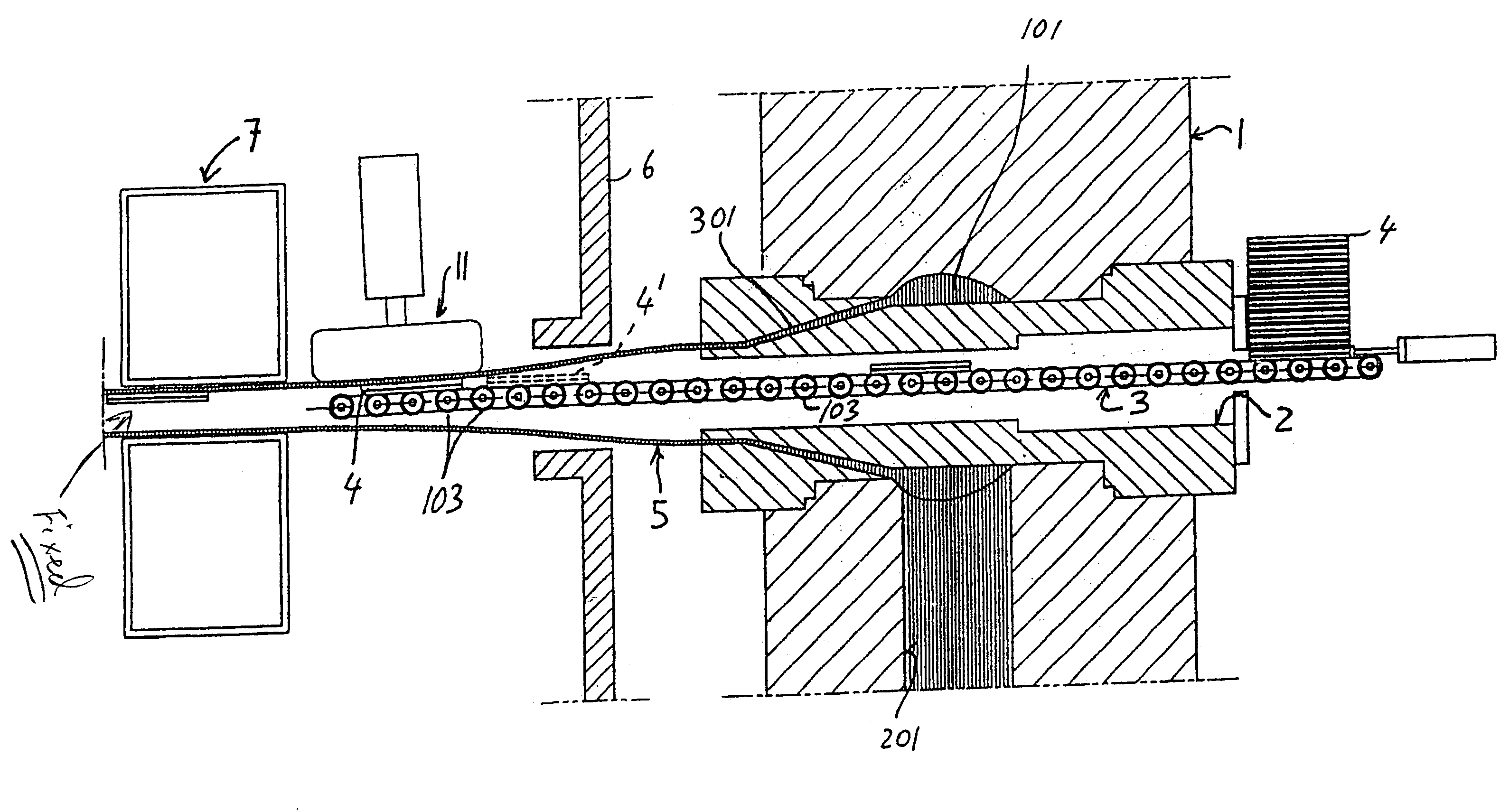
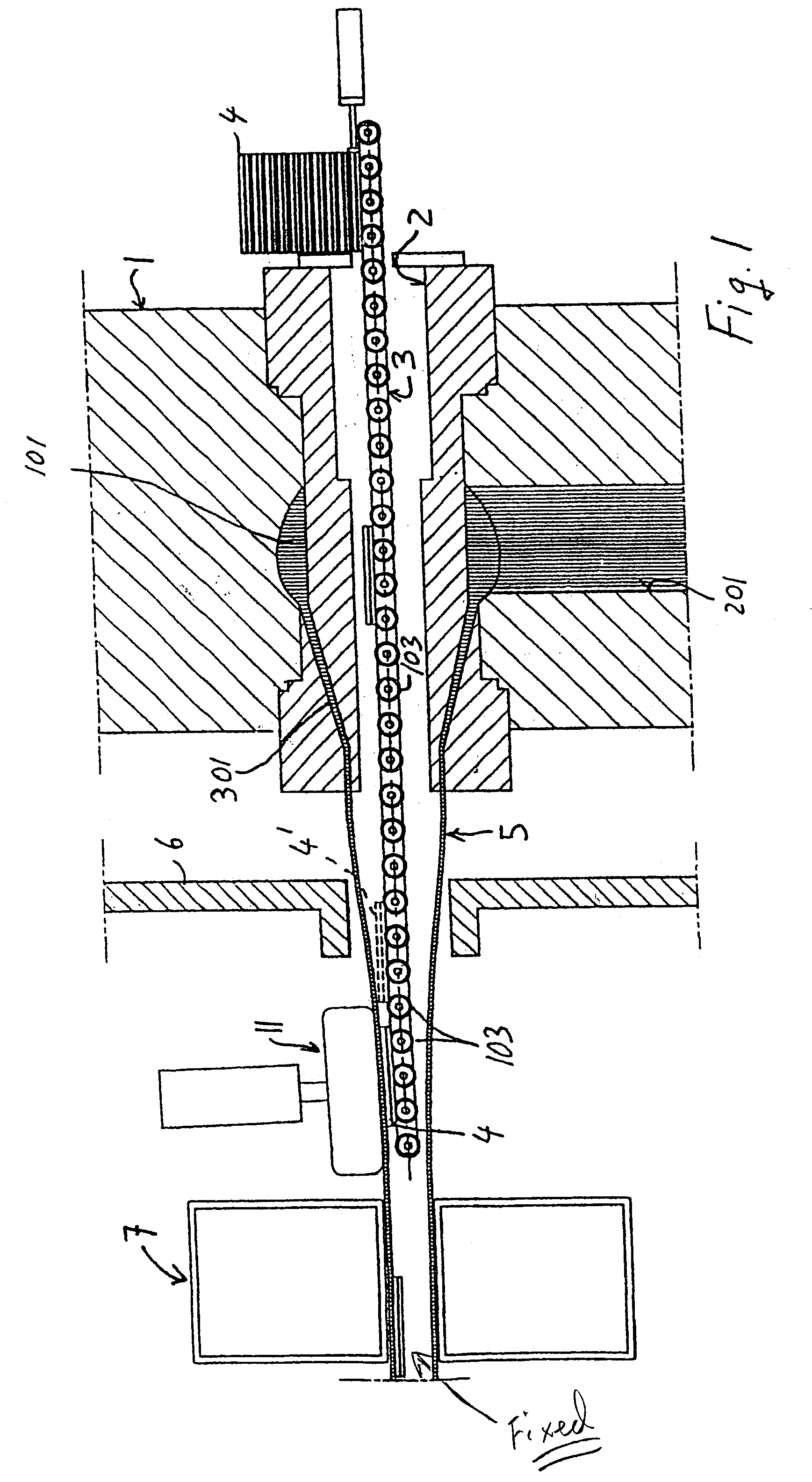
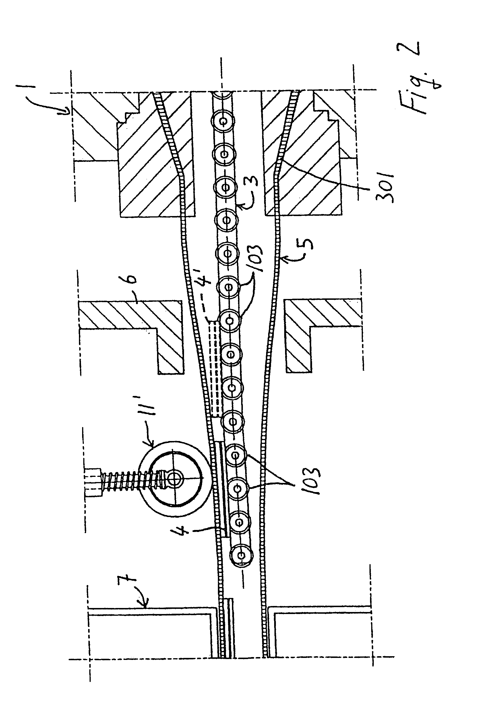
[0063]A plant for fabricating trickle irrigation pipes by extrusion, such as that described in state of the art patents EP 0 344 605 and / or U.S. Pat. No. 5,271,786, comprises an extruding head 1, having an annular chamber 101 and a radial conduct 201 for feeding plastic at the machinable state. The annular chamber 101 axially extends to an annular drawing conduct 301, whereof a continuous pipe comes out. In a coaxial position with respect to the annular conduct 301 and to the annular chamber 101, the extruding head 1 has a central through hole 2, wherein means 3 are supported for guiding a succession of plastic dripping elements 4. The guide means 3 extend from an end whereat the dripping elements 4 are charged, which is outside the extrud...


PUM

PropertyMeasurementUnit
Fractionaaaaaaaaaa
Lengthaaaaaaaaaa
Forceaaaaaaaaaa

Abstract

The invention relates to a method for fabricating a drip irrigation pipe, comprising a pipe (5) wherein a plurality of dripping elements (4) are bound, communicating with the outside through holes formed in the pipe wall. The method according to the invention provides that the pipe (5) is extruded and the individual dripping elements (4) are bound therein by consecutively feeding the dripping elements (4) inside the pipe through the extruding head (1). The speed of the dripping elements (4) is higher than that of the pipe upon extrusion at least in the area of first contact between the pipe and the dripping elements (4). The invention also relates to a plant for implementing said method.

Description

BACKGROUND OF THE INVENTION[0001]The invention relates to a method for fabricating drip irrigation pipes, or similar, comprising the following steps:[0002]a) Extruding a plastic pipe through an extruding head;[0003]b) Progressively reducing the pipe, from the diameter coming out of the extruding head to a final diameter which provides the extruded pipe with a conical shape for a certain initial length.[0004]c) Inserting a plurality of dripping elements consecutively and keeping pace with the advance of the extruded pipe, through the extruding head and into the extruded pipe;[0005]d) Advancing each dripping element to an area of the pipe, whereat each dripping element is brought to contact with a predetermined area of the inner surface of the pipe, while having a predetermined speed relative to the speed of the pipe when contact occurs;[0006]e) Cooling the pipe with the dripping elements;[0007]f) Perforating the pipe where the dripping elements are provided.[0008]Some methods for fab...

Claims


Application Information

Patent Timeline
IPC IPC(8): B29C48/09B29C48/10B29C48/157
CPCB29L2023/22B29C48/09B29C48/10B29C48/0021B29C48/157B29C48/913B29C48/9135B29C48/903B29C48/908
Inventor GIUFFRE′, CARMELO
Owner GIUFFRE CARMELO
Why Eureka
Try Eureka