Hydrocarbon bleed emission scrubber with low restriction

a scrubber and hydrocarbon technology, applied in the direction of combustion-air/fuel-air treatment, other chemical processes, separation processes, etc., can solve the problems of release of bleed emissions, minute levels of hydrocarbons remain, unsatisfactory emissions, etc., and achieve the effect of substantially reducing the bleed emissions of an evaporative canister and high efficiency

Inactive Publication Date: 2005-05-24
DELPHI TECH IP LTD
View PDF19 Cites 48 Cited by
  • Summary
  • Abstract
  • Description
  • Claims
  • Application Information

AI Technical Summary

Benefits of technology

[0014]An advantage of the present invention is that bleed emissions from an evaporative canister are substantially reduced.
[0015]Another advantage of the present invention is the hydrocarbon emissions scrubber is substantially less restrictive to the flow of fluid than a typical auxiliary canister, thereby rendering the

Problems solved by technology

If this flow of air is left untreated and is allowed to escape directly into the atmosphere, undesirable emissions occur.
However, minute levels of hydrocarbons remain stored in the sorbent material of a purged evaporative canister.
The air carries the hydrocarbon heel out of the canister and into the atmosphere, thereby resulting in the release of bleed emissions.
However, in order to achieve sufficient hydrocarbon capacity, auxiliary canisters are generally highly restrictive to the flow of air.
Bypassing an auxiliary canister requires the addition of valving and

Method used


Image

  • Hydrocarbon bleed emission scrubber with low restriction
  • Hydrocarbon bleed emission scrubber with low restriction
  • Hydrocarbon bleed emission scrubber with low restriction

Examples


Embodiment Construction

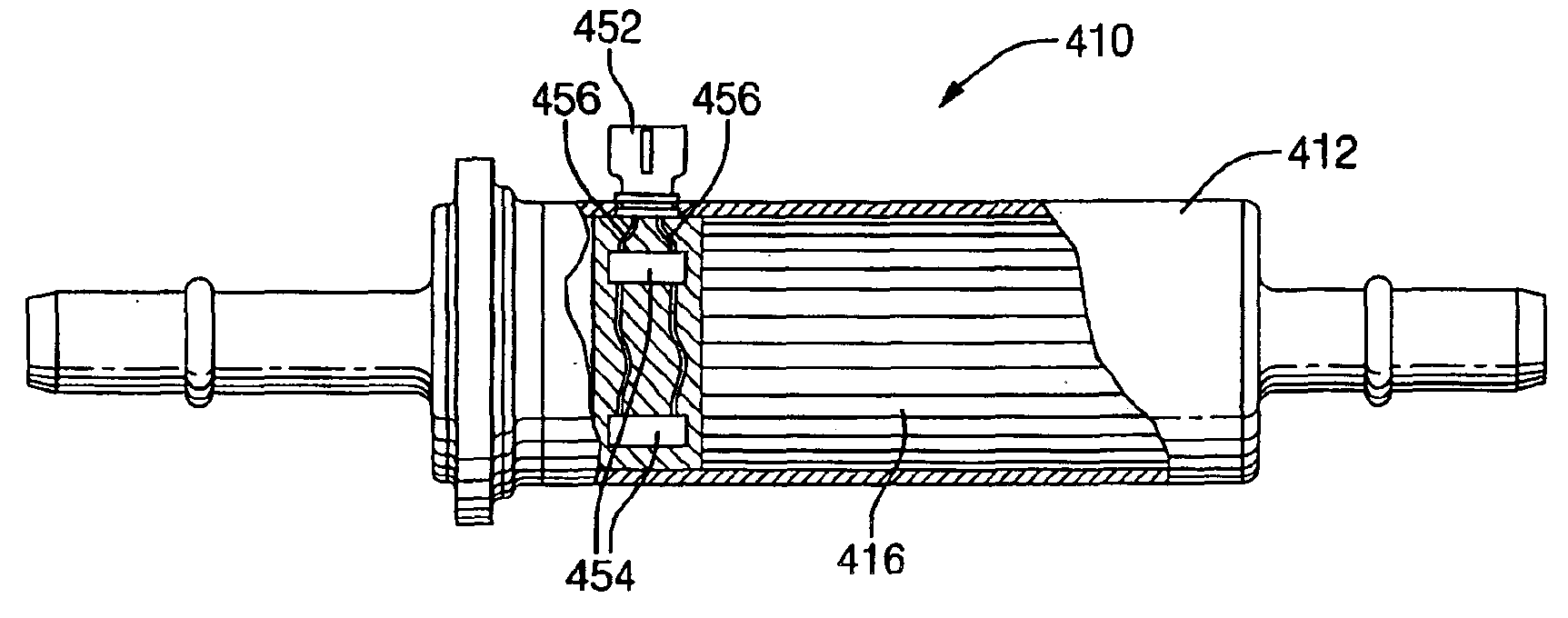
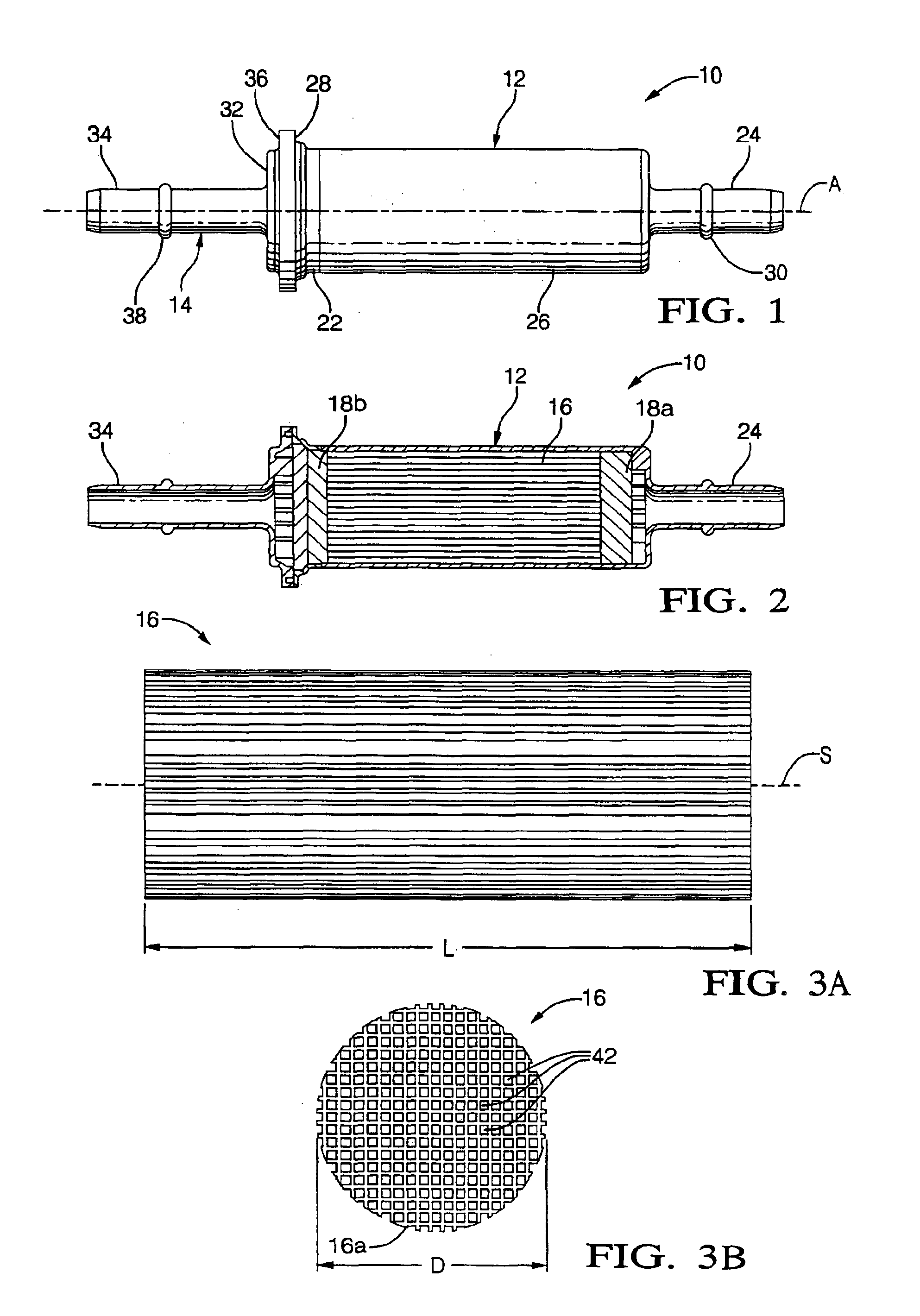
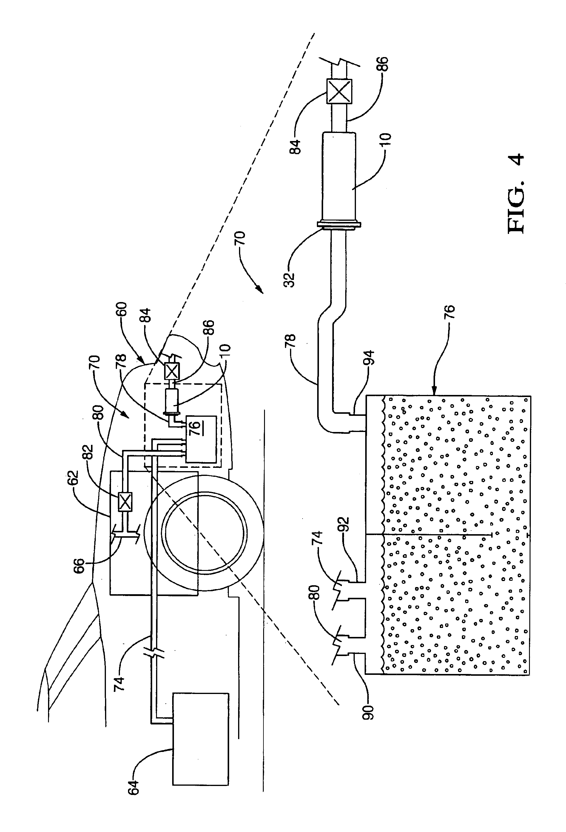
[0031]Referring now to the drawings, and particularly to FIGS. 1 and 2, there is shown one embodiment of a hydrocarbon emissions scrubber of the present invention. Hydrocarbon emissions scrubber 10 (hereinafter referred to as HC scrubber 10) includes housing 12, cap 14, scrubber element 16, and flow diffusers 18a and 18b. Generally, and as will be described more particularly hereinafter, HC scrubber 10 is for use in an evaporative emissions control system of a motor vehicle. HC scrubber 10 is fluidly connected to an evaporative canister of the evaporative emissions control system, and strips residual fuel vapor and / or hydrocarbons from the air flowing from the evaporative canister before discharging the air into the atmosphere.

[0032]Housing 12 is an elongate, substantially cylindrical cup-shaped member having longitudinal central axis A. Housing 12 includes open, flanged end 22, tubular housing end 24 and cylindrical sidewall 26. Flanged end 22 and tubular housing end 24 are interco...


PUM


Abstract

A hydrocarbon emissions scrubber for use in an evaporative emissions control system of a motor vehicle includes a scrubber element having an elongate body. The body defines a plurality of passageways for the flow of fluid therethrough. The plurality of passageways are one of coated with or constructed of a sorbent material. The sorbent material is adsorptive of hydrocarbons.

Description

CROSS REFERENCE TO RELATED APPLICATIONS[0001]This application claims the benefit of U.S. Provisional Patent Application Ser. No. 60 / 192,917, filed Mar. 29, 2000.TECHNICAL FIELD[0002]The present invention relates to evaporative emissions control systems in motor vehicles.BACKGROUND OF THE INVENTION[0003]Motor vehicles emit hydrocarbons as a result of the evaporation of fuel. Generally, such evaporative emissions result from the venting of fuel vapors from the fuel tank due to diurnal changes in ambient pressure and / or temperature, the vaporization of fuel by a hot engine and / or exhaust system, and the escape of fuel vapors during refueling of the vehicle. The venting of fuel vapor from the fuel tank due to diurnal pressure and / or temperature changes (i.e., diurnal emissions) is responsible for a majority of evaporative emissions. Diurnal changes in pressure and / or temperature cause air to flow into and out of the fuel tank. Air flowing out of the fuel tank inevitably carries fuel vap...

Claims


Application Information

Patent Timeline
IPC IPC(8): B01D53/04F02M25/08
CPCB01D53/0415F02M25/0854B01J20/20B01J20/2803B01D53/0438B01D53/0446B01D2253/102B01D2253/25B01D2253/3425B01D2257/702B01D2258/01B01D2259/40081B01D2259/40086B01D2259/40096B01D2259/402B01D2259/4516B01D2259/4566
Inventor MEILLER, THOMAS C.COVERT, CHARLES H.LABINE, SUSAN S.
Owner DELPHI TECH IP LTD
Why Eureka
Try Eureka