
Image processing apparatus, image processing method, and storage medium for color matching

a technology of image processing and color matching, which is applied in the direction of colour-separation/tonal correction, digital marking record carriers, instruments, etc., can solve the problems of inability to realize color matching in consideration of how to use ink dependent on a printer (device), and the appearance of tint rather changes

Inactive Publication Date: 2005-05-24
CANON KK
View PDF14 Cites 39 Cited by
  • Summary
  • Abstract
  • Description
  • Claims
  • Application Information

AI Technical Summary

Benefits of technology

[0017]a control means for controlling a method of the color matching processing and a method of the image data separation, according to a kind of input image.

Problems solved by technology

In an actual processing system, when image data is subjected to color gamut mapping pixel by pixel, an enormous processing time is necessary.
However, in the above conventional case, since the color matching is performed in the device-independent L*a*b* color space, it is impossible to realize color matching in consideration of how to use inks dependent on a printer (device).
Further, in such the conventional color gamut mapping as shown in FIG. 18, in the case where the compression is performed without dislocating the hue angles in an a*b* plane, since the uniform color space such as the L*a b* color space does not completely reflect a human's sight characteristic, there is a problem that an appeared tint rather changes because the compression is performed without dislocating the hue angle.
However, there is a problem that a chroma of a highlight area or a shadow area disappears extremely.
However, there is a problem that unbalance of the lightness occurs due to the hue, whereby feeling of wrongness appears in reproduction image quality.

Method used


Image

  • Image processing apparatus, image processing method, and storage medium for color matching
  • Image processing apparatus, image processing method, and storage medium for color matching
  • Image processing apparatus, image processing method, and storage medium for color matching

Examples


first embodiment

(First Embodiment)

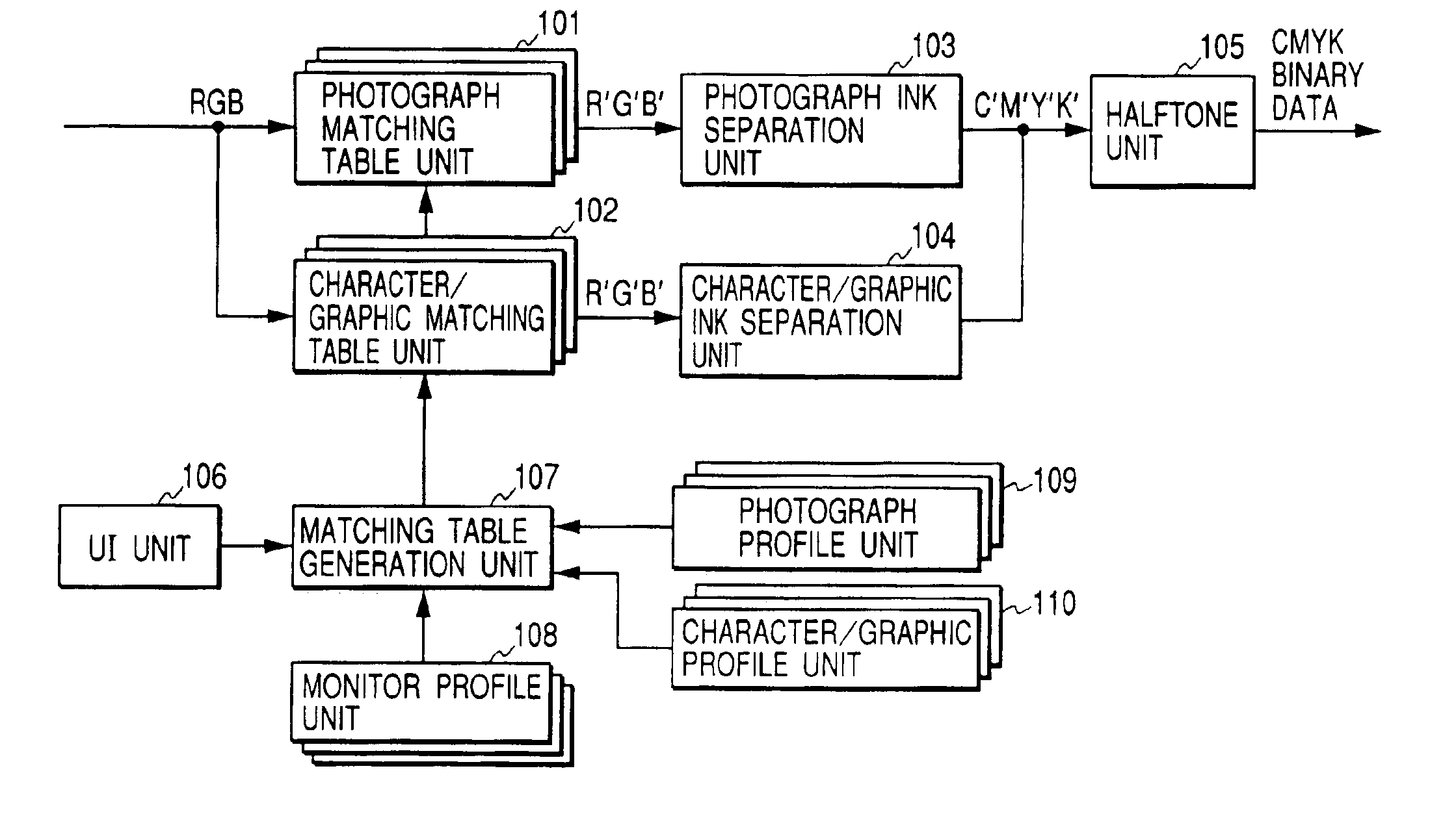
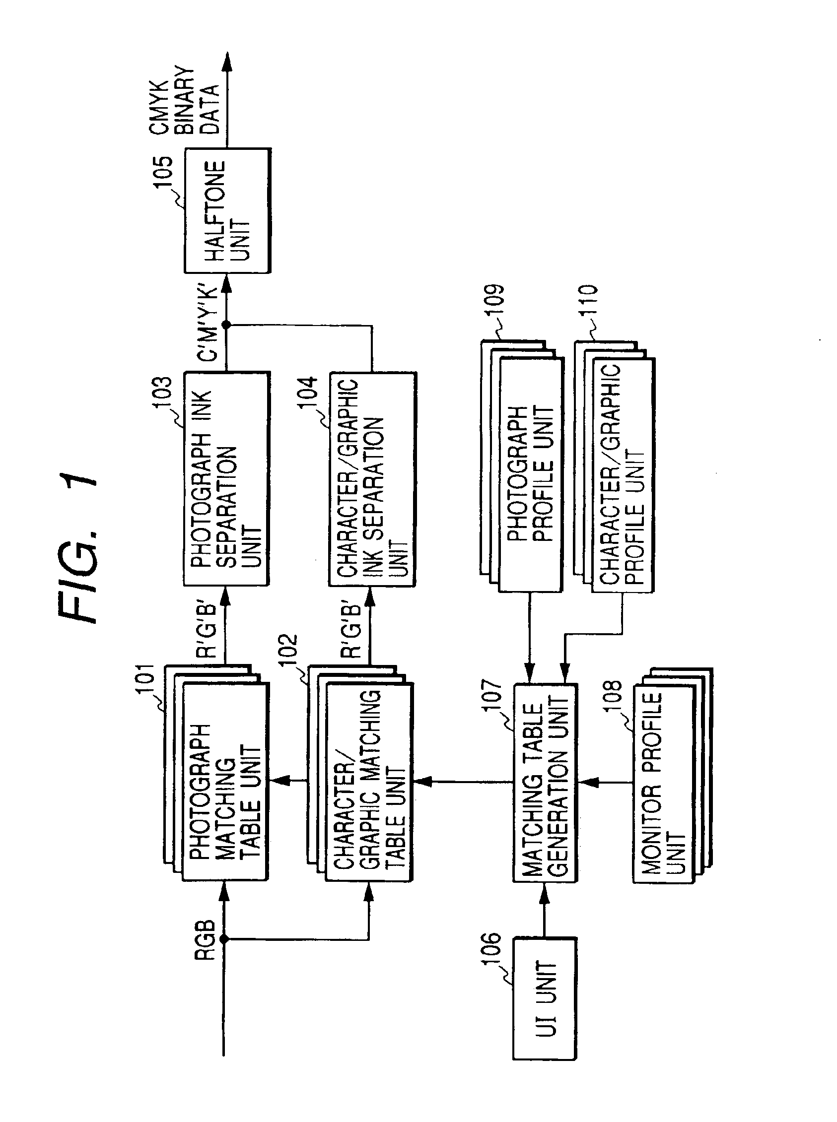
[0042]FIG. 1 is a block diagram showing a structure of the first embodiment of the present invention. In FIG. 1, numeral 101 denotes a matching table unit for a photograph (called a photograph matching table unit hereinafter), numeral 102 denotes a matching table unit for a character and a graphic (called a character / graphic matching table unit hereinafter), numeral 103 denotes an ink separation (or decomposition) unit for a photograph (called a photograph ink separation unit hereinafter), numeral 104 denotes an ink separation (or decomposition) unit for a character and a graphic (called a character / graphic ink separation unit hereinafter), and numeral 105 denotes a halftone unit. The halftone unit 105 performs processing to match the number of bits of input data with the number of bits manageable by the printer in a halftone method such as a dither method, an error diffusion method or the like. Numeral 106 denotes a UI (user interface) unit by which a user selects...

second embodiment

(Second Embodiment)

[0058]In the first embodiment, the means for realizing the color matching is provided independently of the means for realizing the ink separation, whereby the printout processing can be performed at high speed. The second embodiment proposes to simplify a hardware structure for reduction in costs and color reproduction equivalent to the first embodiment.

[0059]FIG. 4 is a block diagram showing a structure of the second embodiment. In FIG. 4, numeral 401 denotes a matching synthesis table unit for a photograph (called a photograph matching synthesis table unit hereinafter), numeral 402 denotes a matching synthesis table unit for a character and a graphic (called a character / graphic matching synthesis table unit hereinafter), and numeral 403 denotes a matching synthesis table generation unit. It should be noted that, like FIG. 1, numerals 105, 106, 108, 109 and 110 denote a halftone unit, a UI unit, a monitor profile unit, a photograph profile unit and a character / gr...

third embodiment

(Third Embodiment)

[0064]In the first embodiment, the hardware structures as shown in FIG. 5 are-used for the photograph ink separation unit 103 and the character / graphic ink separation unit 104. However, it is possible to use a three-input and four-output table for converting R, G and B data into C, M, Y and K data and a hardware structure for executing multidimensional interpolation calculation.

[0065]FIG. 6 is a flow chart for explaining processing to generate a three-input and four-output ink separation table which converts the R, G and B data into the C, M, Y and K data. In FIG. 6, symbol S601 denotes a start step, symbol S602 denotes a grid data generation step of generating R, G and B grid data, symbol S603 denotes a luminance / density conversion step, symbol S604 denotes a judgment step of judging whether or not the table to be generated is for the photograph, symbol S605 denotes a UCR quantity setting step for a character and a graphic, symbol S606 denotes a UCR quantity setti...


PUM


Abstract

An image processing apparatus comprises a color matching processing unit for performing color matching processing according to color reproduction characteristics of input and output devices, a color separation unit for separating image data subjected to the color matching processing, into color components corresponding to recording agents used by the output device, and a control means for controlling a method of the color matching processing and a method of the image data separation, according to a kind of input image. Thus, it is possible to perform the color matching processing and the color component separation according to the kind of input image, thereby realizing the color matching in consideration of how to use the recording agents and the satisfactory color matching according to a human's sight characteristic.

Description

BACKGROUND OF THE INVENTION[0001]1. Field of the Invention[0002]The present invention relates to image processing apparatus and method which perform processing concerning color matching, and a storage medium.[0003]2. Related Background Art[0004]A color matching method is the method to match tints of two devices (e.g., a monitor and a color printer each having a different color reproduction range) with each other. When the color reproduction range of the monitor is compared with the color reproduction range of the color printer, the color reproduction range of the monitor is generally wider than the color reproduction range of a printing output by the color printer, whereby a part of colors represented by the monitor can not be reproduced by the printer.[0005]Thus, various methods to realize color matching between the monitor and the color printer are designed. Concretely, in these methods, in a device-independent uniform color space such as CIE-L*a*b* color system, color gamut mappi...

Claims


Application Information

Patent Timeline
Patent Type & Authority Patents(United States)
IPC IPC(8): H04N1/60G06T1/00H04N1/46
CPCH04N1/6072
Inventor SAITO, KAZUHIROMAKITA, TAKESHIMATSUOKA, HIROCHIKA
Owner CANON KK
Learn More