Camera lens assembly

a technology for camera lenses and lens assemblies, applied in the field of camera lens assemblies, can solve the problems of reducing the cleaning requirement of invention, reducing the assembling error, and so as to reduce the assembling error and reduce the cleaning requirement. , the effect of increasing the yield of manufacturing the camera lens assembly

Active Publication Date: 2005-05-24
CALLAHAN CELLULAR L L C
View PDF9 Cites 74 Cited by
  • Summary
  • Abstract
  • Description
  • Claims
  • Application Information

AI Technical Summary

Benefits of technology

[0010]In view of the foregoing, the invention is to provide a camera lens assembly, which can solve the problem of high manufacturing cost caused by the high cleanness requirement of the filter.
[0012]As mentioned above, the camera lens assembly of the invention installs an optical filter module in between the first lens and the second lens. Comparing with the prior art, the blocking issue would not occur when the sensor receives the light beam(s). Thus, the cleanness requirement of the invention can be reduced. In addition, the assembling error can be decreased, which results in the increased yield of manufacturing the camera lens assembly and the decreased cost of the camera lens assembly.

Problems solved by technology

In addition, the assembling error can be decreased, which results in the increased yield of manufacturing the camera lens assembly and the decreased cost of the camera lens assembly.

Method used


Image

  • Camera lens assembly
  • Camera lens assembly
  • Camera lens assembly

Examples


Embodiment Construction

[0020]The present invention will be apparent from the following detailed description, which proceeds with reference to the accompanying drawings, wherein the same references relate to the same elements.

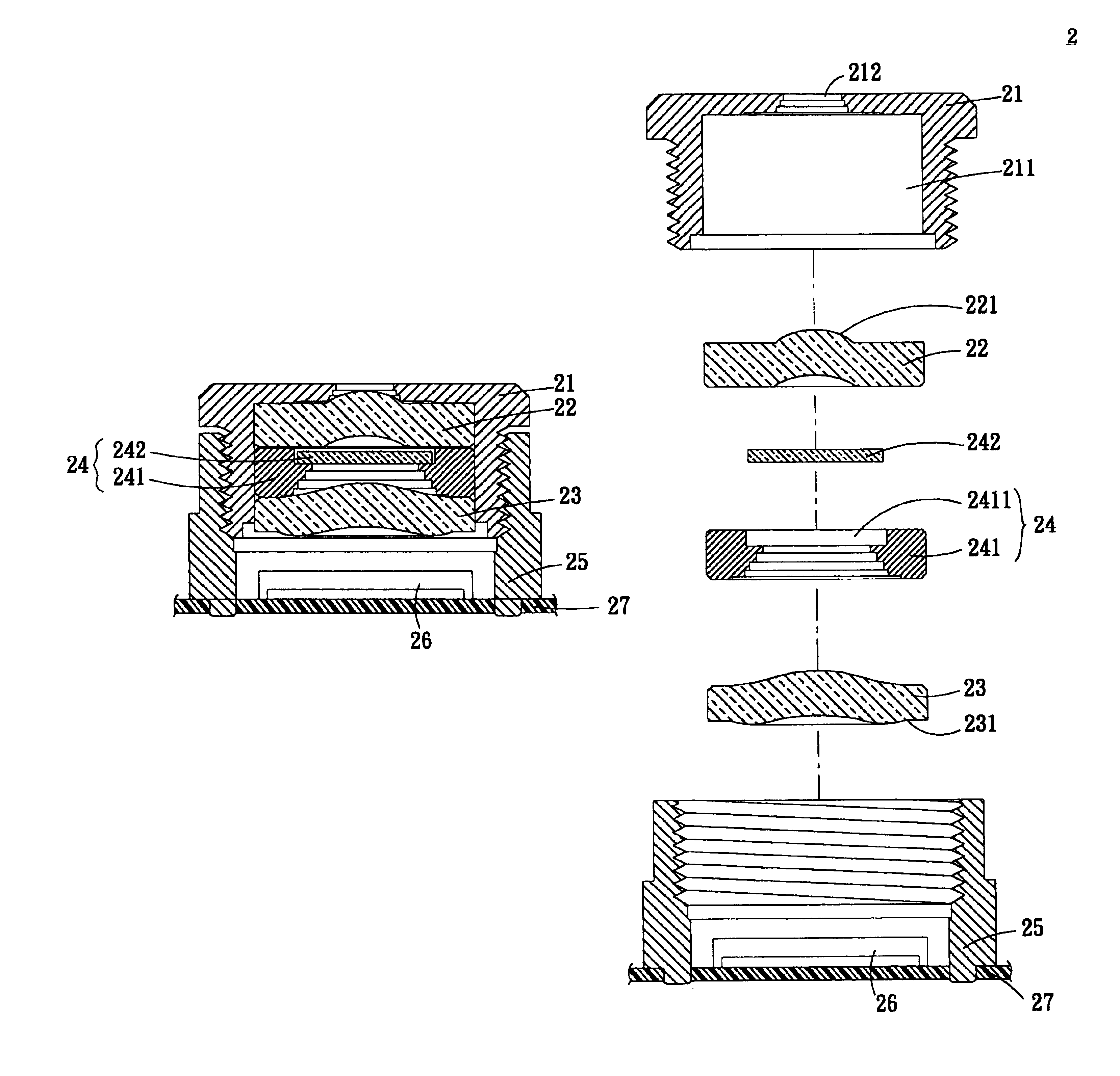
[0021]With reference to FIG. 3 and FIG. 4, the camera lens assembly 2 according to the embodiment of the invention includes a barrel 21, a first lens 22, a second lens 23, an optical filter module 24, and a holder 25. The barrel 21 includes a first container 211 and a diaphragm 212, and is connected to the holder 25. The holder 25 connects to a substrate 27 and is adhered to the substrate 27. The substrate 27 is a printed circuit board or a flexible board. In this embodiment, the holder 25 is adhered to the substrate 27 with UV glue. Moreover, other usable method for adhering the holder 25 and the substrate 27 should be included in the scope of the invention.

[0022]The first lens 22 is accommodated in the first container 211 and includes a first surface 221. The first surface 221 is a ...


PUM


Abstract

A camera lens includes a barrel, a first lens, a second lens and an optical filter module. The barrel includes a first container and a diaphragm. The first lens is disposed in the first container next to the diaphragm. The second lens is disposed in the first container with a distance from the first lens. The optical filter module is disposed in the first container between the first and the second lenses.

Description

BACKGROUND OF THE INVENTION[0001]1. Field of Invention[0002]The invention relates to a camera lens assembly and, in particular, to a camera lens assembly, which has an optical filter module positioned between a first lens and a second lens.[0003]2. Related Art[0004]With reference to FIG. 1, a conventional camera lens assembly 1 includes a barrel 11, a first lens 12, a spacer 13, a second lens 14, a blocking filter 15, a sensor 16, and a holder 17.[0005]The barrel 11 connects to the holder 17 and includes a container 111 and a diaphragm 112. The first lens 12 is accommodated in the container 111 and is next to the diaphragm 12. The spacer 13 is accommodated in the container 111 and is next to the first lens 12. The second lens 14 is accommodated in the container 111 and is next to the spacer 13. The blocking filter 15 is set on the holder 17 and is next to the second lens 14.[0006]The sensor 16 is disposed on a substrate 18, which is a printed circuit board or a flexible board. The h...

Claims


Application Information

Patent Timeline
Patent Type & Authority Patents(United States)
IPC IPC(8): G02B7/02G02B7/00
CPCG02B7/021G02B7/006
Inventor LIN, JUI-HSINHSU, CHING-PIN
Owner CALLAHAN CELLULAR L L C
Why Eureka
Try Eureka