Filter coefficient generator

a filter coefficient and generator technology, applied in pulse manipulation, pulse technique, instruments, etc., can solve the problems of inability to timely generate filter coefficients necessary for changes such as display modes and image formats, and inability to timely generate filter coefficients for changes

Inactive Publication Date: 2005-05-24
LG ELECTRONICS INC
View PDF4 Cites 5 Cited by
  • Summary
  • Abstract
  • Description
  • Claims
  • Application Information

AI Technical Summary

Benefits of technology

[0011]An object of the present invention is to provide a filter coefficient generator that timely generates filter coefficients necessary for frequent display mode and image format change.

Problems solved by technology

Filter coefficient generators according to the prior art, however, are not able to timely generate filter coefficients necessary for the changes such as display modes and image formats.
Therefore, the image quality may be impaired in a transition period.

Method used


Image

  • Filter coefficient generator
  • Filter coefficient generator
  • Filter coefficient generator

Examples


Embodiment Construction

[0024]Reference will now be made in detail to the preferred embodiments of the present invention, examples of which are illustrated in the accompanying drawings.

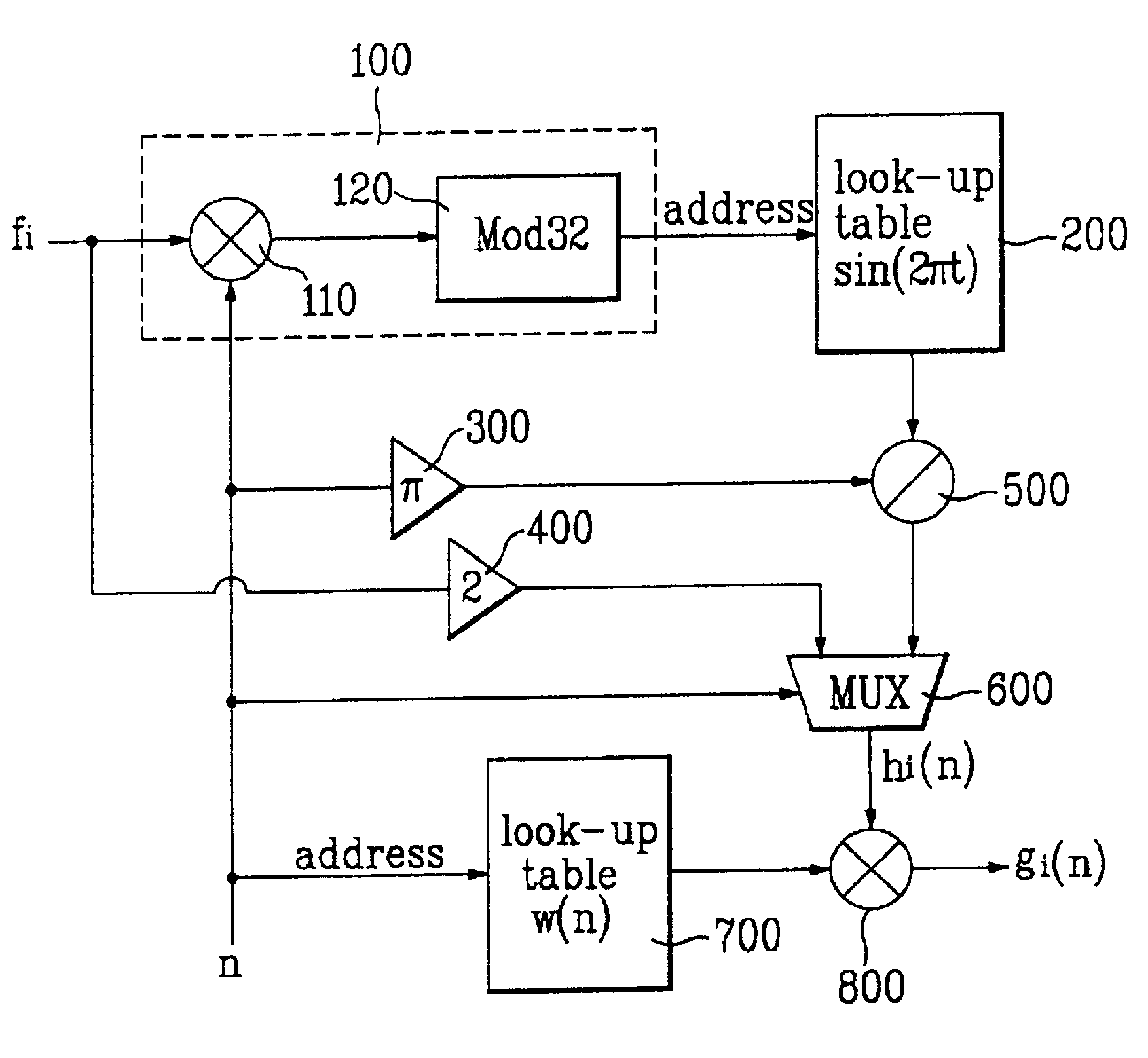
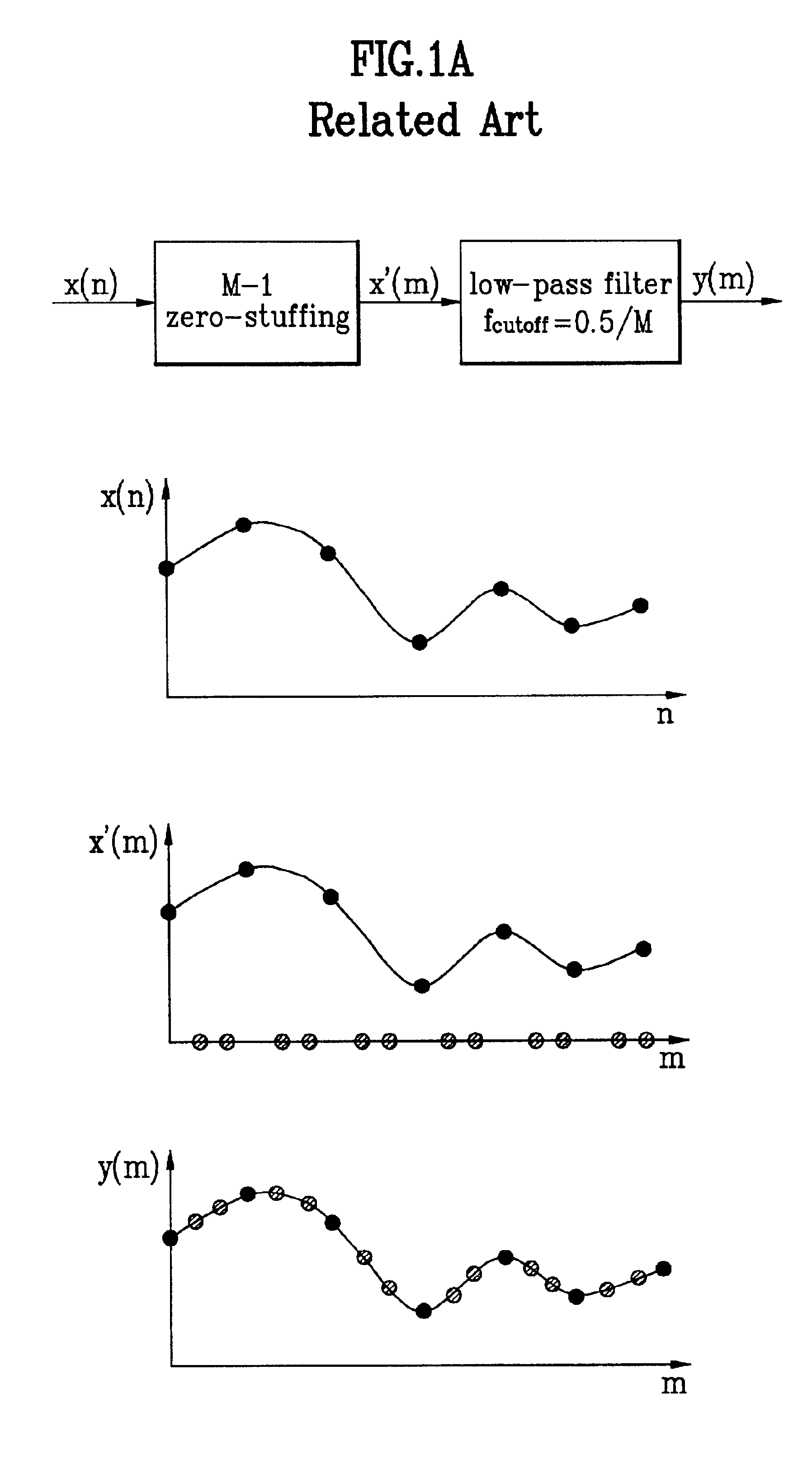
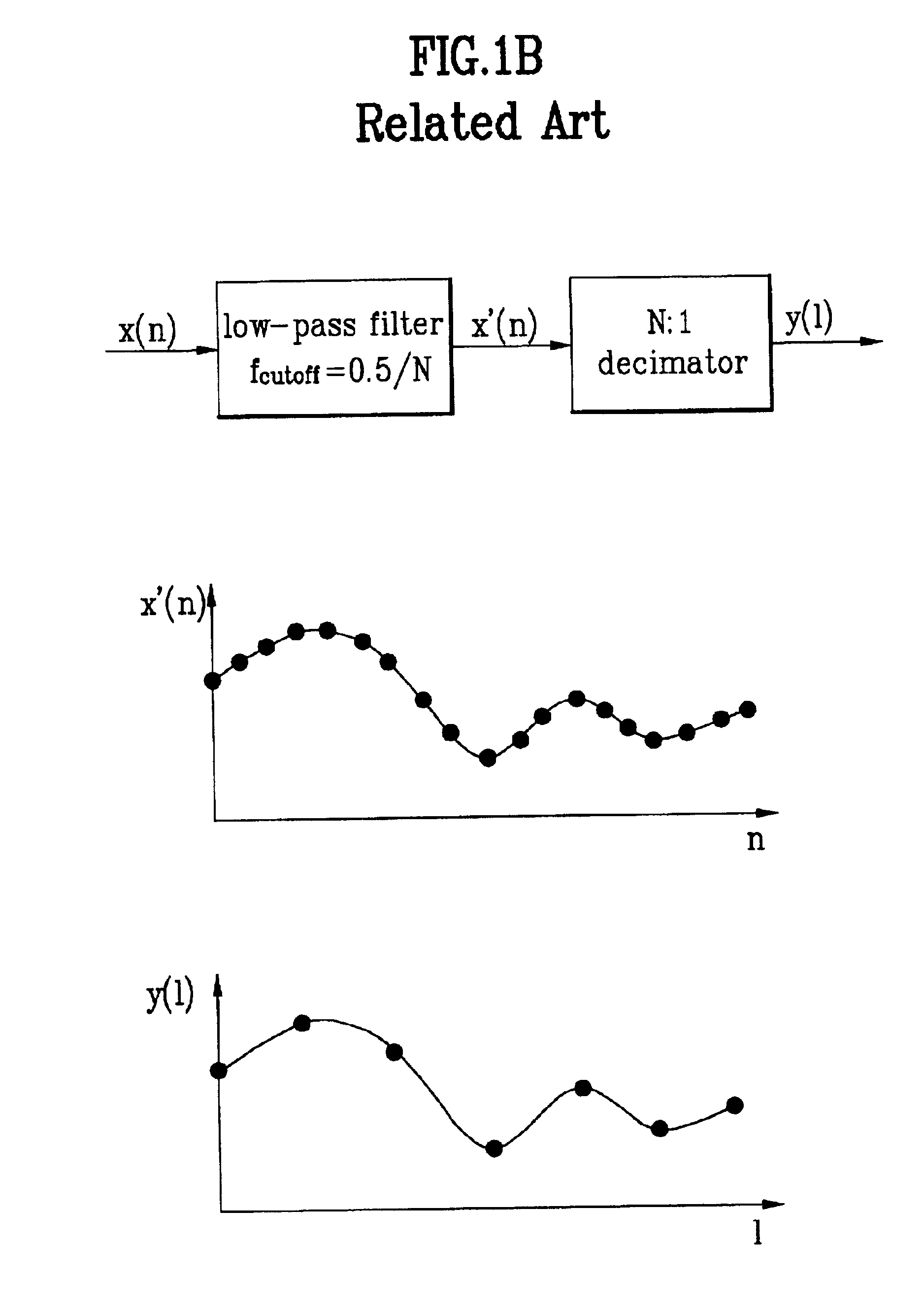
[0025]Filters used for sampling rate conversion caused by display mode and image format changes generally require low-pass characteristics, and the values of filter coefficients must be promptly updated based on the rates of input and output data. However, the present invention is nonly limited only to low-pass filters, but rather involves general filters that include any one of low-pass, high-pass, and band-pass characteristics.

[0026]FIG. 3 illustrates the magnitude function of a filter having f1 and f2 as its low and high cutoff frequencies. The impulse response of the filter can be obtained by using an inverse Fourier transformation as follows. [Eq.1]h⁡(n)=F-1⁢{H⁡(f)}=∫-f2f2⁢ⅇj⁢ ⁢2⁢ ⁢π⁢ ⁢fn⁢ⅆf-∫-f1f1⁢ⅇj⁢ ⁢2⁢ ⁢π⁢ ⁢fn⁢ⅆf=2⁢f2⁢sin⁢ ⁢c⁡(2⁢π⁢ ⁢f2⁢n)-2⁢f1⁢sin⁢ ⁢c⁡(2⁢π⁢ ⁢f1⁢n)=sin⁡(2⁢π⁢ ⁢f2⁢n)π⁢ ⁢n-sin⁡(2⁢π⁢ ⁢f1⁢n)π⁢ ⁢n

where F−1...


PUM


Abstract

An apparatus and method for generating finite impulse response (FIR) filter coefficients are presented. The apparatus includes an address generator that multiplies a desired cutoff frequency f by an integer n to generate an address, a first look-up table that generates a sine function value of the address, a divider that divides the sine function value by n*pi, a multiplexer that generates an impulse response function value by selecting one of a value produced from the divider and 2*f based on an outside control signal, and a multiplier that multiplies the impulse response function value by a corresponding window function value to generate an nth filter coefficient for the FIR filter.

Description

BACKGROUND OF THE INVENTION[0001]1. Field of the Invention[0002]The present invention relates to a filter coefficient generator, and more particularly, to a filter coefficient generator that promptly generates necessary filter coefficients in response to frequent sampling rate (frequency) changes of digital signals.[0003]2. Background of the Related Art[0004]Supporting various display modes (e.g., PIP, POP, Zoom-In, Zoom-Out, and etc.) and display formats have become essential factors for digital televisions of these days. Up / down sampling rate conversion techniques are often used when it is necessary to change image sizes in order to make proper changes to the various display modes / formats in the digital televisions.[0005]FIGS. 1 and 2 show general up / down sampling rate conversion techniques widely used to make such changes.[0006]FIG. 1A illustrates a 1:M up sampling process of a digital signal when M is equal to 3. After M-1 zero-stuffing step is performed, wherein M-1 zero-valued...

Claims


Application Information

Patent Timeline
Patent Type & Authority Patents(United States)
IPC IPC(8): H03H17/02H04N7/24
CPCH03H17/0226H03H17/0227H04N7/0102H04N7/0117
Inventor KIM, SANG YEON
Owner LG ELECTRONICS INC
Why Eureka
Try Eureka