Plastic heat exchanger

a heat exchanger and plastic technology, applied in the field of heat exchangers, can solve the problems of not being able to change the location of the nozzle without expensive tooling changes, no means are provided for sealing the separator divider against leakage, and none of the prior-art inventions have provision for grounding a metal tube bundle to the engin

Active Publication Date: 2005-05-31
R&D ENTERPRISES
View PDF32 Cites 55 Cited by
  • Summary
  • Abstract
  • Description
  • Claims
  • Application Information

AI Technical Summary

Problems solved by technology

Nor can the location of the nozzles be changed without expensive tooling changes.
No means is provided for sealing the separator divide...

Method used


Image

  • Plastic heat exchanger
  • Plastic heat exchanger
  • Plastic heat exchanger

Examples


Embodiment Construction

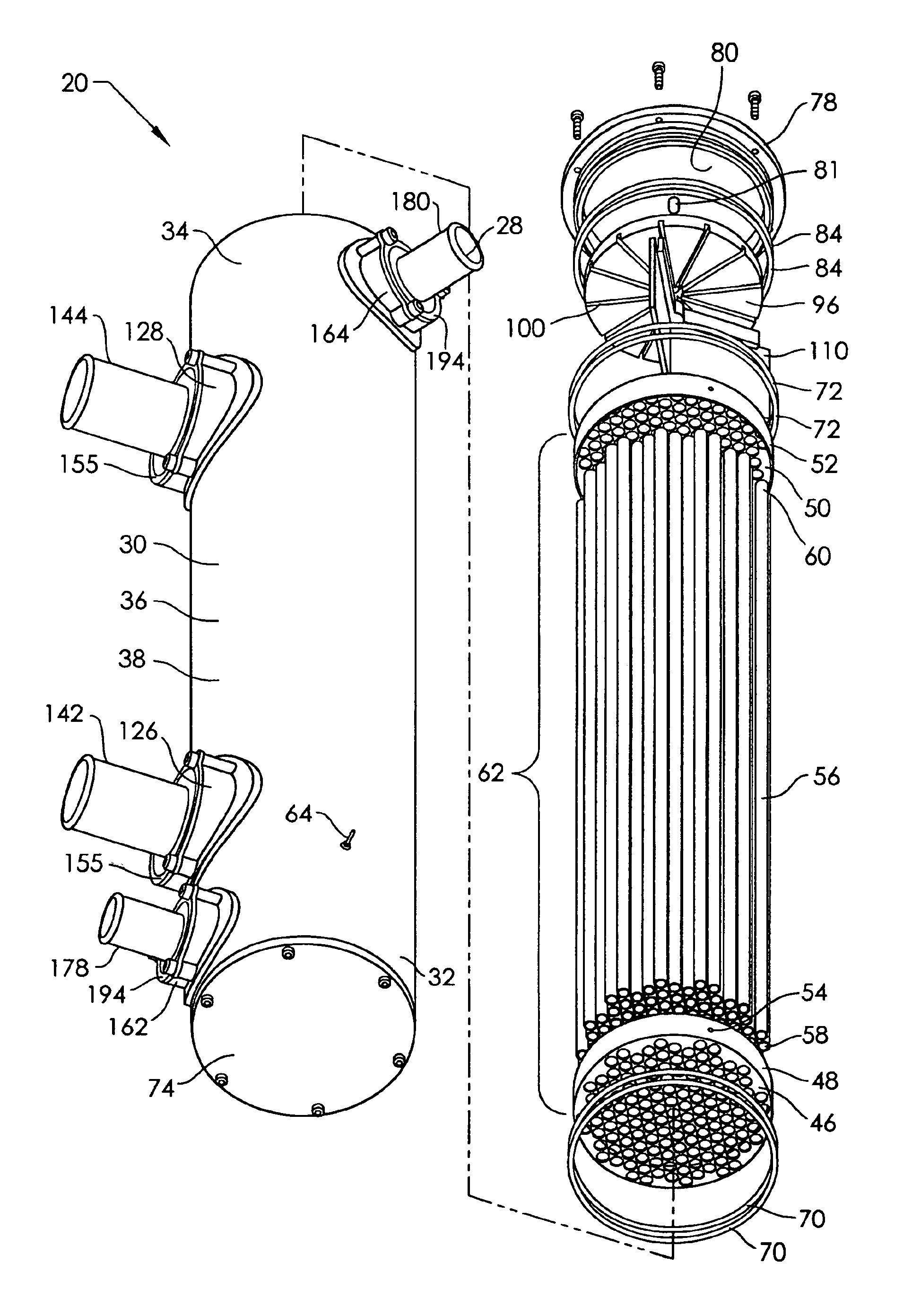
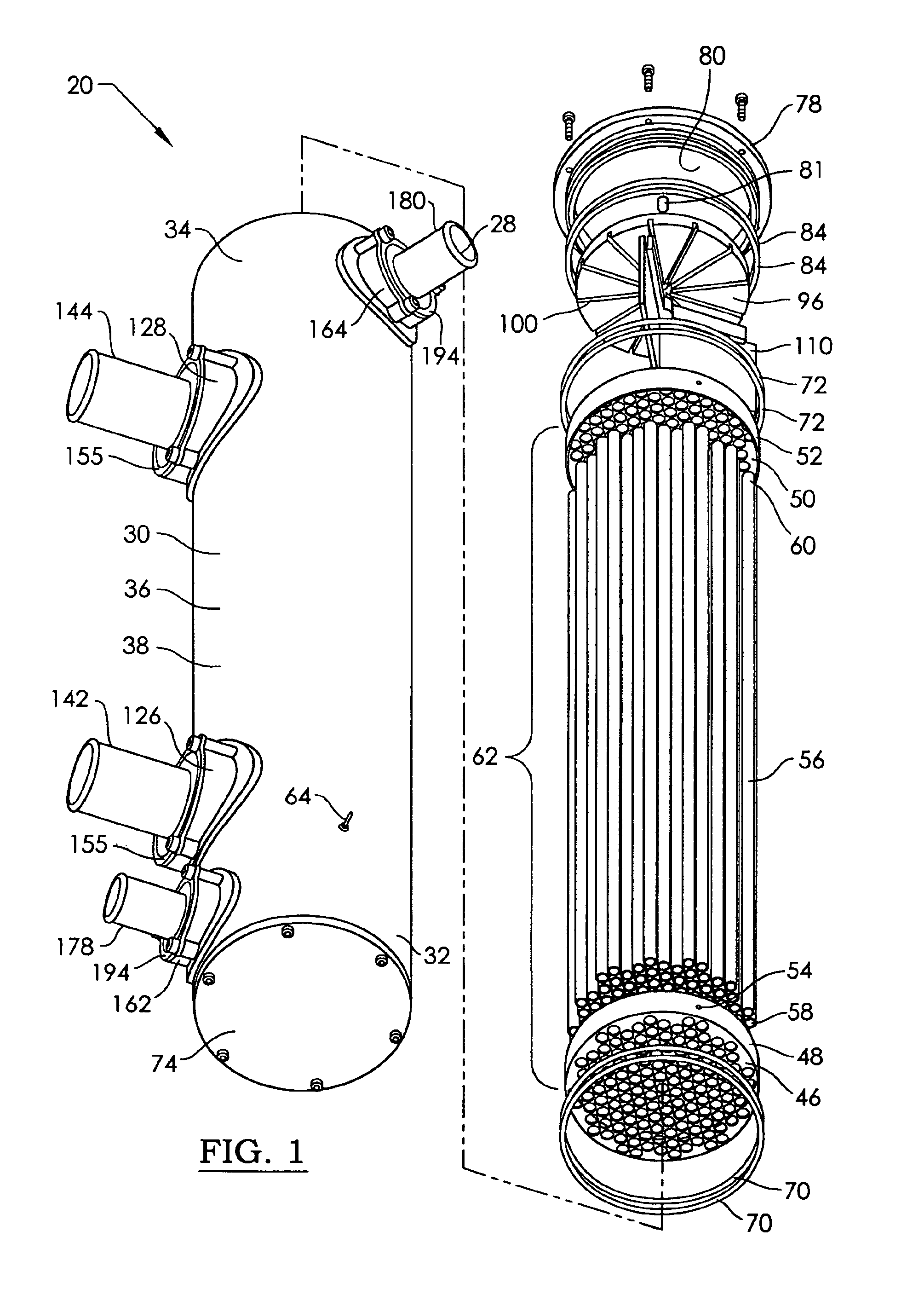
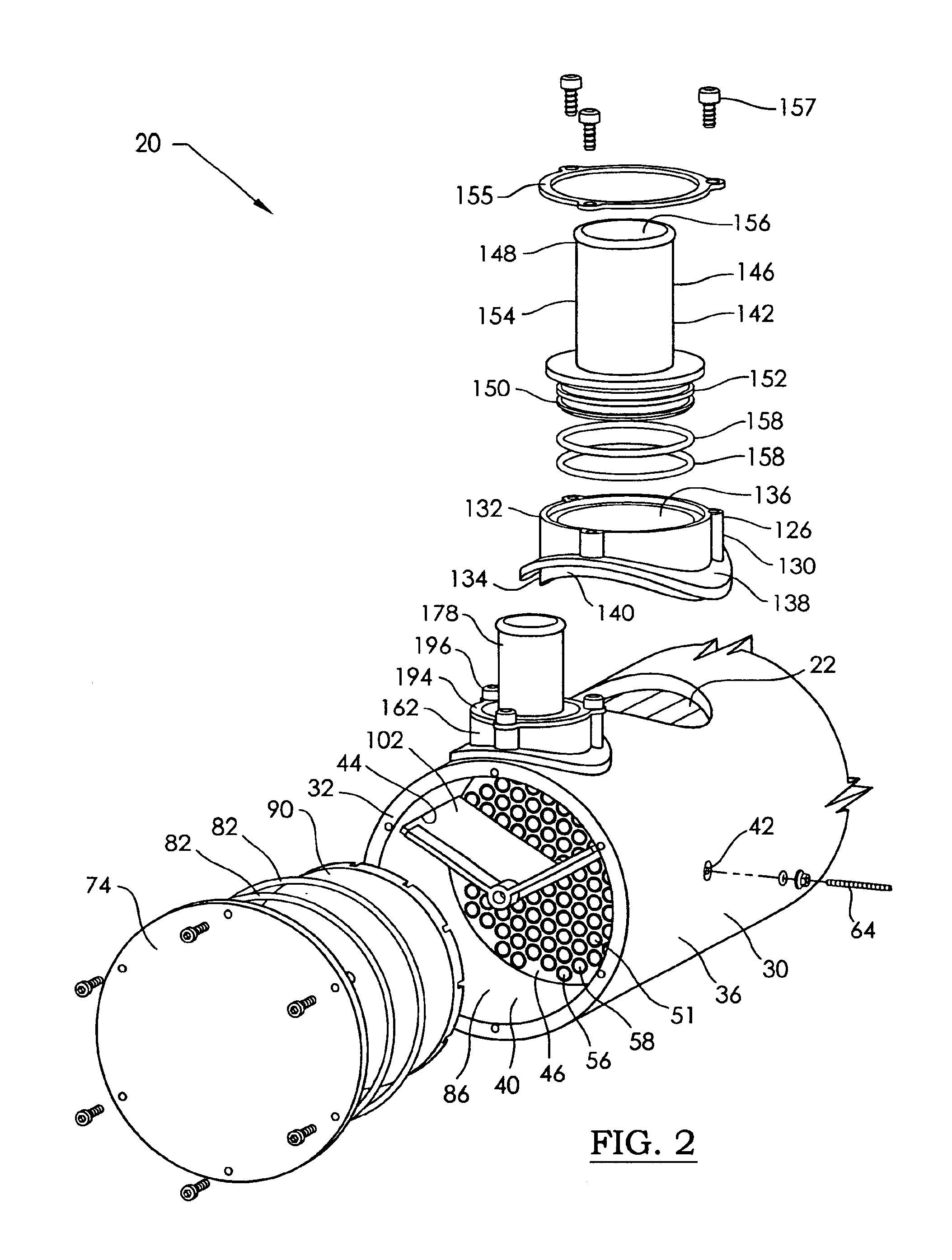
[0042]Referring now to the drawing, and especially to FIGS. 1, 2, 4, 5, and 6 thereof, a shell and tube heat exchanger constructed in accordance with the invention is shown at 20. The heat exchanger is used for transferring heat between a shell coolant flowing around the outside of the tubes, and a tube coolant flowing inside the tubes. The heat exchanger is for use particularly with a marine engine. The coolants will be carried by external conduits between the engine and the heat exchanger. The shell coolant will typically be a glycol-based engine coolant. The tube coolant will typically be seawater. It is to be understood that the tube coolant can be the engine coolant, and the shell coolant can be the seawater. It is also to be understood that the heat exchanger can be used for a variety of applications, such as a stationary engine, or a process plant. Further, the coolants can be any heat exchanging fluid medium. The heat exchanger 20 has first 22 and second 24 shell coolant pas...


PUM

PropertyMeasurementUnit
Timeaaaaaaaaaa
Angleaaaaaaaaaa
Heataaaaaaaaaa

Abstract

A shell and tube heat exchanger has two shell coolant and two tube coolant passageways communicating with a cavity in a shell. Removably received in the shell cavity is a tube bundle with tube headers. A locating screw extends through the shell to engage a locating recess in one tube header. The screw locates the tube bundle angularly about the central axis and longitudinally along the central axis, and is also used to electrically ground the tube bundle. An end cover, a flow separator, and resilient disc to take up thermal expansion are installed in each end of the shell to direct coolant through the tube bundle in multiple passes. Receivers with rotatable connectors are bonded to each shell coolant and tube coolant passageway. Angled connector nozzles can be connected to external conduits in any orientation.

Description

CROSS-REFERENCE TO RELATED APPLICATIONS[0001]Not applicable.STATEMENT REGARDING FEDERALLY SPONSORED RESEARCH FOR DEVELOPMENT[0002]Not applicable.BACKGROUND OF THE INVENTION[0003]This invention relates to the field of heat exchangers, and more particularly to a shell and tube heat exchanger with plastic components.[0004]Shell and tube heat exchangers are commonly used with marine engines for cooling. For use in seawater, they isolate the engine cooling system from the corrosive effects of the salt water. They are also found on stationary auxiliary generators, and in industrial and chemical process plants. Engine cooling systems typically use a mixture of ethylene glycol and de-ionized water as coolant. Ambient cooling water may be salty or fresh. Shell and tube heat exchangers are well known, and have taken a variety of configurations in the past. Some examples of heat exchangers in the prior art are shown in the following patents:[0005]Schroeder, U.S. Pat. No. 5,746,270, discloses a...

Claims


Application Information

Patent Timeline
IPC IPC(8): F28F21/06F28F9/02F28F9/04F28F21/00F28D7/16F28D7/00
CPCF28D7/1607F28F9/0202F28F9/0219F28F9/0246F28F21/067F28F9/0248F28F2280/02F28F2275/20F28F2265/24
Inventor COX, RICHARD D.
Owner R&D ENTERPRISES
Why Eureka
Try Eureka