Hollow pole driver

Inactive Publication Date: 2005-05-31
TCB FLASH
View PDF18 Cites 36 Cited by
  • Summary
  • Abstract
  • Description
  • Claims
  • Application Information

AI Technical Summary

Benefits of technology

[0008]My device includes a ring permanently mounted to the hollow pole in a generally mid-section of the pole, a hammer sleeve for sliding over the pole and ring, and a pair of weights (top and bottom) mounted within the hammer sleeve at opposed sides of the ring. The hammer sleeve slides about the axis of the pole in two opposed directions. Depending on the direction of force being applied, the hammer

Problems solved by technology

Depending on the hardness of any given ground surface, the driving of a pole into the ground can be difficult.
If an individual merely uses human applied force, the pole may not be driven to the desired depth.
Unfortunately, the use of a hammer on a hollow pole may result in damage to the hollow pole.
For instance, if the pole is a lightweight and hollow pole us

Method used


Image

  • Hollow pole driver
  • Hollow pole driver
  • Hollow pole driver

Examples


Embodiment Construction

[0017]Throughout the following detailed description, the same reference numerals refer to the same elements in all figures.

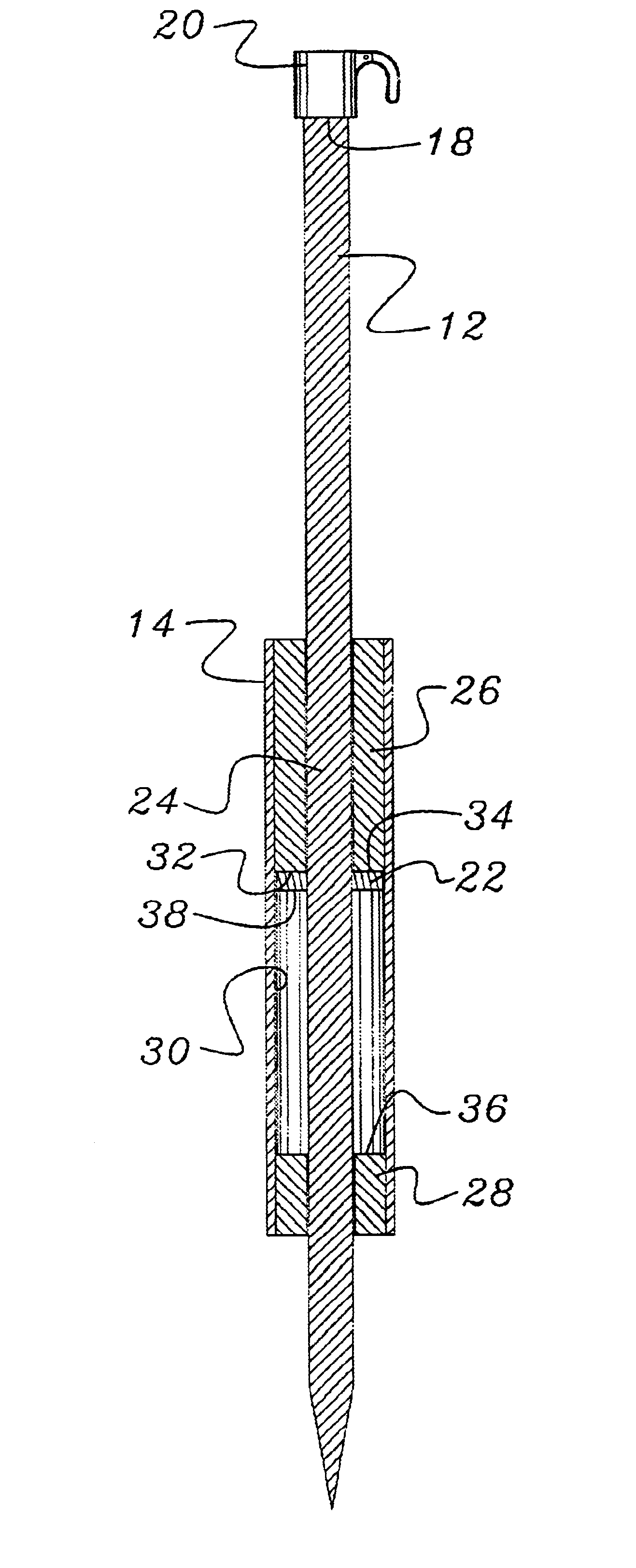
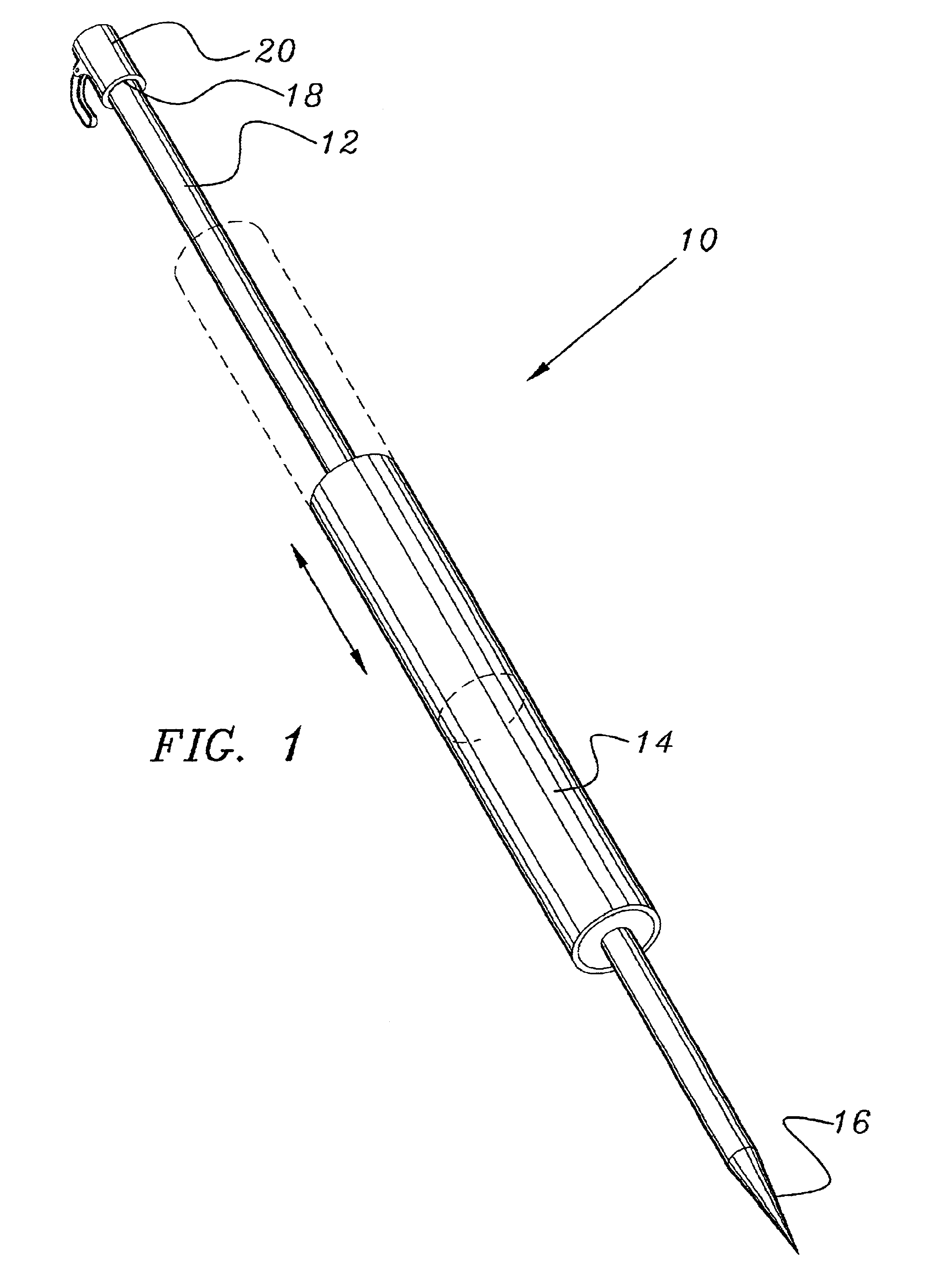
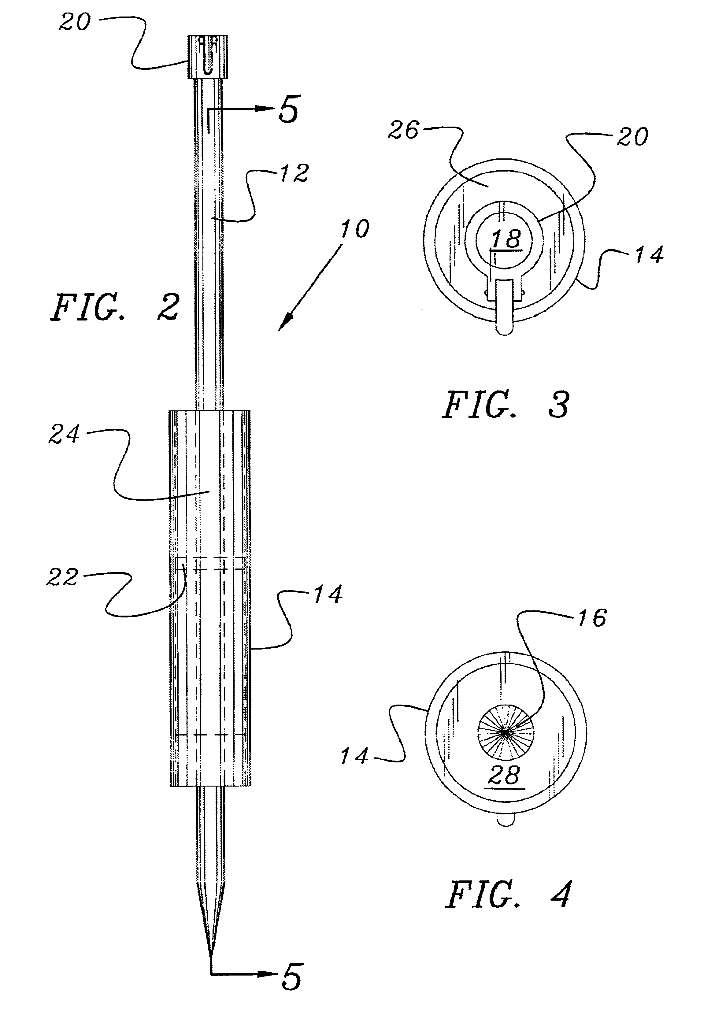
[0018]Referring to FIG. 1, the hollow pole driver device 10 of the present invention is shown. Driver 10 includes a hollow pole 12 and a hammer sleeve 14. Pole 12 has an outer circumference less than and a length greater than that of hammer sleeve 14. Both pole 12 and hammer sleeve 14 are cylindrical in shape. In the preferred embodiment, driver 10 is used with beach or yard umbrellas. Accordingly to the preferred embodiment, driver 10 further includes a pointed bottom end 16 for inserting within the ground and a cylindrically-shaped top end 18 having a clamping mechanism 20 inserted thereon. Referring to FIG. 7, clamping mechanism 20 permits an additional pole 40 to be inserted into and supported by driver device 10 once hollow pole 12 is driven into the ground to the desired depth. Additional pole 40 can support a plurality of different items, such as, for exa...


PUM


Abstract

A hollow pole has an open top end and a pointed bottom end; the open top end supports an additional pole. A ring member is permanently mounted about a mid-section of the hollow pole. A hammer sleeve having a length less than that of the hollow pole inserts over the hollow pole and around the ring member. A pair of weights are mounted within opposed ends of the hammer sleeve and surrounds the ring member. The ring member provides an upper and lower limit to the hammer sleeve. With the pointed bottom end of the hollow pole positioned on the ground, the hammer sleeve is pulled upward and slammed downward driving the pole into the ground. To remove the pole, the procedure is reversed whereby the hammer sleeve is slammed upwards away from the ground. The additional pole can support a plurality of different items, such as, for example, a beach umbrella or an attachment to a volley ball net.

Description

BACKGROUND OF THE INVENTION[0001]1. Field of the Invention[0002]This invention relates to a pole driver. More particularly, it relates to a device for attaching to a hollow pole for driving the pole into the ground and removing it therefrom.[0003]2. Description of Prior Art[0004]Depending on the hardness of any given ground surface, the driving of a pole into the ground can be difficult. If an individual merely uses human applied force, the pole may not be driven to the desired depth. If the pole is solid, it is known that an individual can strike the top portion of the pole with a hammer to apply the necessary force for driving the pole to the desired depth. Unfortunately, the use of a hammer on a hollow pole may result in damage to the hollow pole. For instance, if the pole is a lightweight and hollow pole used for recreational use, such as, for example, a beach umbrella, the use of a hammer to strike the top portion of the hollow umbrella pole will most certainly lead to damage t...

Claims


Application Information

Patent Timeline
IPC IPC(8): E04H12/22B25D1/16
CPCE04H12/2215B25D1/16
Inventor MCCARTHY, MICHAEL PARTICK
Owner TCB FLASH
Why Eureka
Try Eureka