
Container with tamper resistant lid

a container and lid technology, applied in the direction of lids, liquid handling, closures using stoppers, etc., can solve the problems of easy rupture of sections, inability to meet the needs of use, and inability to meet the needs of use, and achieve excellent sealing

Inactive Publication Date: 2005-05-31
NELSON JAMES L
View PDF7 Cites 49 Cited by
  • Summary
  • Abstract
  • Description
  • Claims
  • Application Information

AI Technical Summary

Benefits of technology

[0018]The purpose of the present invention is to provide a container with tamper resistant lids that are extremely secure but may be easily removed to provide access to the contents of the container.
[0021]Because the tamper evident tear strip or band is locked into place and is protected with small bumps or steps around the outside edge forming latches and its reverse action to keep in place, there is no need for the heat links of the zipper lid between the tabs or flaps. This elimination of the heat links makes the manufacturing of the lid simpler and eliminates the need for a heating unit in the lid mounting or capping machine.
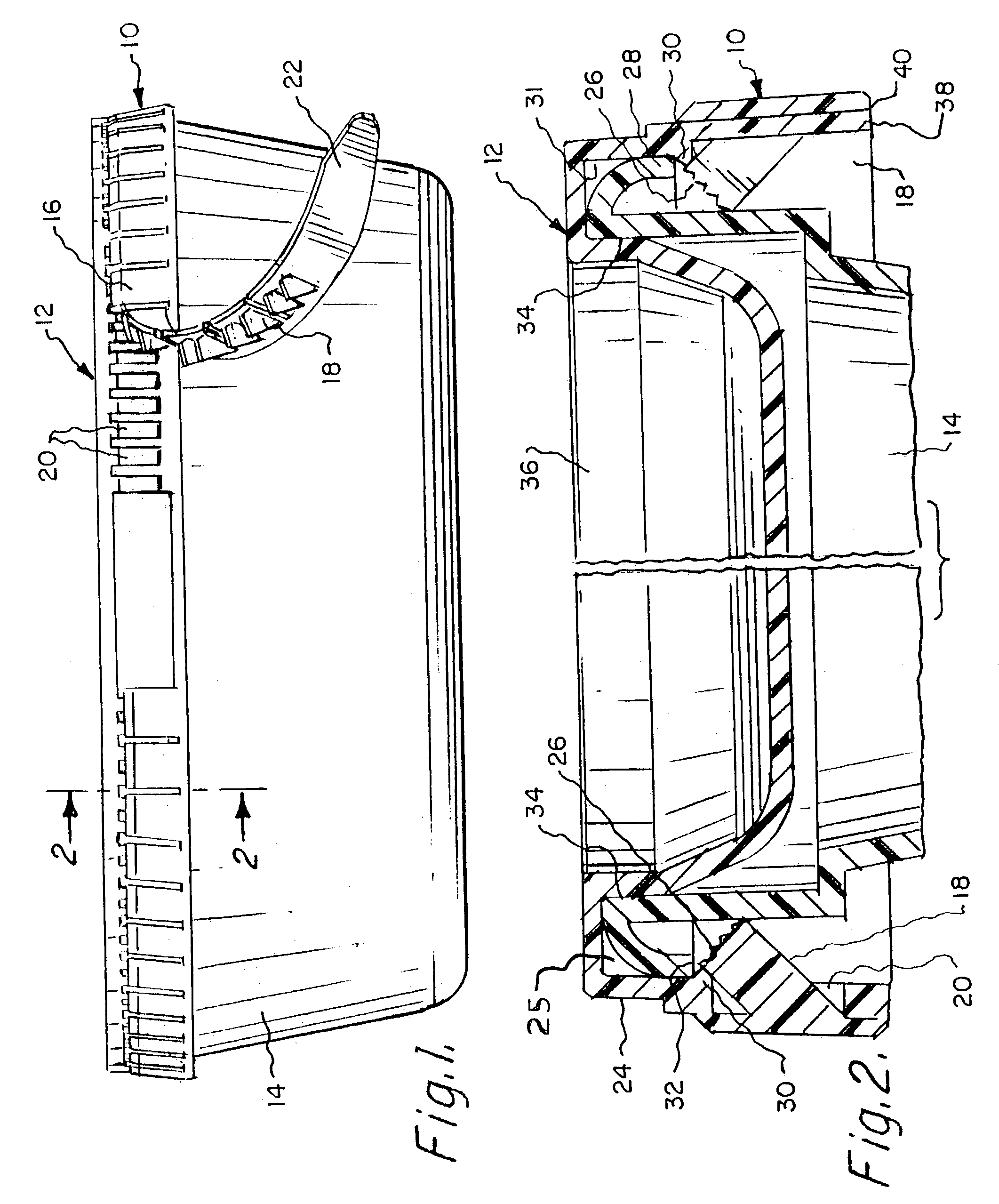
[0023]In addition the lid seals both on the inside and outside of the cup or container providing an excellent seal. The lower inside peripheral edge of the skirt or lip on the lid has a ridge that fits over a flange on the rim of the cup or container and an inside surface that fits inside and engages the inner periphery of the container. The lid has an annulus beneath the skirt that is mounted by pressing it down guiding the container into the annulus then folding the tear strip upward so that the spurs and the stepped edges engage the slots in the lid. This locks the tear strip in place around the periphery of the cup or container. A surface adjacent the ridge in the annulus securely engages an outer surface of the flange on the rim of the container. These surfaces in the annulus under the lid skirt provide a secure, tight seal with or without the tamper resistant band or strip on the lid.

Problems solved by technology

Present methods have achieved some modicum of success but a disadvantages that they are not as secure as they could be and are in some cases costly to use.
One such container having a plastic lid has sections that are easily ruptured to remove the lid.
Any attempt to force the lid off the container will rupture these section and provide evidence of tampering.
However, this system can be defeated by slow, tedious prying of the lid a small section at a time, until a lid is removed without rupturing the tamper evidence seal.
However, this system can be defeated by warming the heat shrinkable sleeve and slowly stretching it until it can be easily removed.
Another disadvantage of the present products is that the more secure they are the more difficult it is to open them and gain access to the contents of the container.
Users have been injured by stabbing or cutting themselves trying to remove the seal.
Another difficulty with this type of arrangement is that it is also difficult to remove and sometimes requires a cutting instrument to pierce the seal.
Thus it is apparent that while the present methods are effective, they have disadvantages in that they can be defeated or if very secure, they are difficult to remove.
However, this method of protecting containers is costly and requires special machinery for mounting the lids on containers.
Thus in addition to the cost of manufacturing the lid, the method of putting the lids on the containers add to the cost of the procedure.
It this container, a tear strip is provided that is extremely difficult to remove without rupturing one or more sections of a tear-strip mounted on the lid.

Method used


Image

  • Container with tamper resistant lid
  • Container with tamper resistant lid
  • Container with tamper resistant lid

Examples


Embodiment Construction

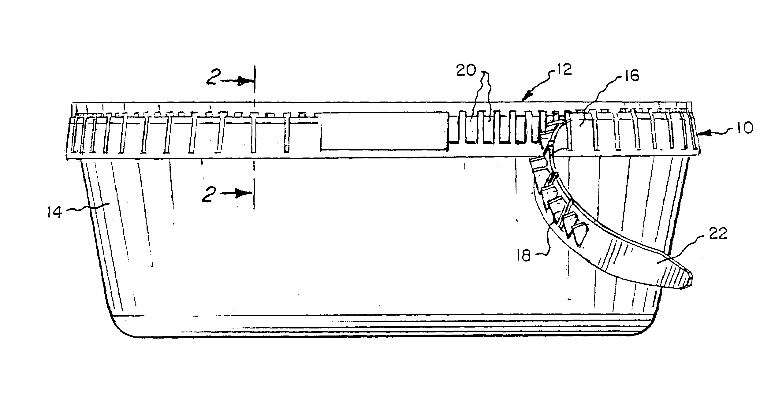
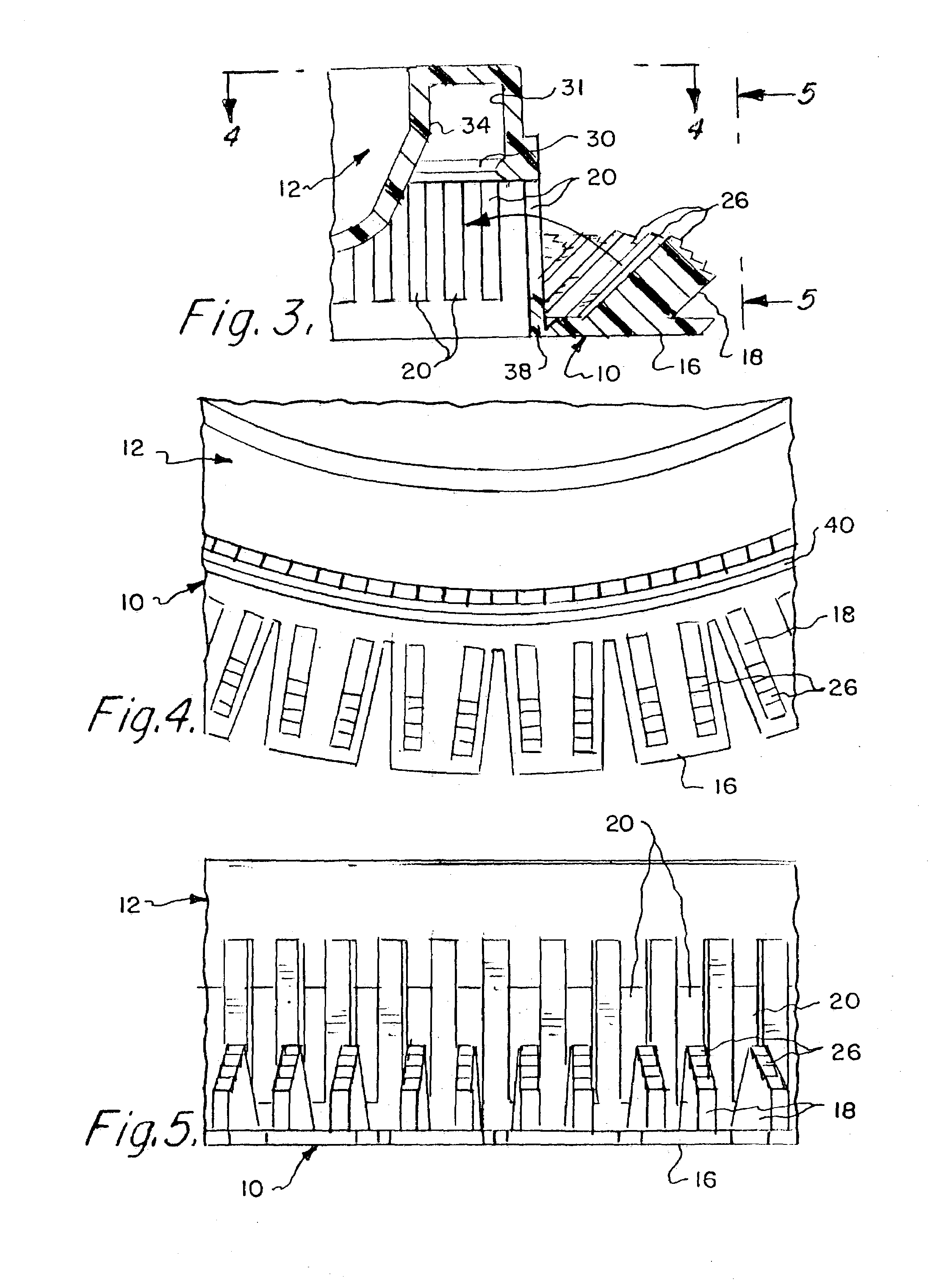
[0036]One embodiment of the invention is illustrated in FIGS. 1 through 5 in which the tamper resistant or tamper evident tear strip 10 is mounted on a peripheral lower edge of a skirt of a container lid and is unique because it locks by folding it up rather than down. Tamper evident tear strip 10 is shown on lid 12 mounted on cup or container 14. Tamper resistant tear strip 10 is separated into a plurality of equal spaced and equal sized tabs 16 having spurs or lugs 18 on one side for engaging slots 20 in the peripheral skirt of lid 12 as will be in greater detail hereinafter. Tamper resistant tear strip 10 is removed from a sealed container by gripping finger pull tab 22 and applying a lateral force. The arrangement shown provides an easily removed tamper resistant tear strip while at the same time providing a very secure lid that looks similar but works quite differently from the zipper lid disclosed and described in U.S. Pat. No. 5,115,934 of the same inventor as the invention d...


PUM


Abstract

A container lid having a tamper evident and tamper resistant band formed of a plurality of equally spaced tabs having spurs that engage the rim of a container with latches formed on the spurs. In one embodiment the tamper evident band is unique because it hinges up instead of down and has a plurality of spurs with a stepped edge forming latches with the spurs engaging slots around the periphery of the lid. The reverse action makes the step edges on the spurs on the inside of tabs formed on the tamper resistant strip pull tighter when any attempt is made to pry or remove the lid from a container or cup. The lid also includes an annulus having interior surfaces that provide an excellent seal both inside and outside of the cup when the tamper resistant band is removed. In a second embodiment a tamper resistant band is formed with a curved surface to engage the exterior surface of the cup and has a plurality of spurs with a detent forming a latch to engage the lower edge of the skirt around the periphery of the lid. Each tab on the tamper resistant and tamper evident band has preferably two spurs.

Description

BACKGROUND OF THE INVENTION[0001]1. Field of the Invention[0002]This invention relates to containers with tamper resistant lids and more particularly relates to a container having a tamper resistant lid with a tear strip secured by latches formed on spurs on the tear strip.[0003]2. Background Information[0004]In recent years, package tampering has resulted in many methods being conceived to protect against tampering and indicate when tampering has occurred. These methods include products sealing and container will make container tamper evident. Any tampering with the seals on the container will be readily apparent so that potential user will be warned. Present methods have achieved some modicum of success but a disadvantages that they are not as secure as they could be and are in some cases costly to use.[0005]One such container having a plastic lid has sections that are easily ruptured to remove the lid. Any attempt to force the lid off the container will rupture these section and ...

Claims


Application Information

Patent Timeline
IPC IPC(8): B65D43/02
CPCB65D43/0256B65D45/20B65D2543/00092B65D2543/00296B65D2543/00796B65D2543/00555B65D2543/00657B65D2543/00685B65D2543/0074B65D2543/00509
Inventor NELSON, JAMES L.
Owner NELSON JAMES L
Learn More