Fluid sampling valve

a sampling valve and flue gas technology, applied in the direction of valve operating means/release devices, couplings, instruments, etc., can solve the problems of exposing the pilot and surrounding environment to both liquid fuel and fuel vapor, none of these drain valves permit the fuel to be returned to its source, and none of these drain valves permit backflow to flush debris or contaminants trapped within the valv

Inactive Publication Date: 2005-05-31
EATON INTELLIGENT POWER LIMITED
View PDF2 Cites 107 Cited by
  • Summary
  • Abstract
  • Description
  • Claims
  • Application Information

AI Technical Summary

Benefits of technology

[0004]A valve for connecting a fluid sampling device to a fluid source is provided that includes a body adapted to be secured to the fluid source and a valve member moveably disposed within the body. In an embodiment of the present invention, the body includes a coupling interface configured to sealingly mate with the fluid sampling device. The valve member is actuated by the fluid sampling device during attachment of the fluid sampling device to the valve body. The fluid sampling device actuated valve member is moveable between a first position in which a flow path between the fluid source and the fluid sampling device is closed and a second position in which the flow path between the fluid source and the fluid sampling device is open. When the fluid flow path is open, the fluid sampling device can withdraw a fluid sample for inspection and return the fluid sample to the fluid source without exposing the fluid to the surrounding environment.

Problems solved by technology

Known drain valves require a cup or bottle to catch the fuel flowing from the valve's drain port, which exposes the pilot and surrounding environment to both liquid fuel and fuel vapor.
None of these drain valves permit the fuel to be returned to its source back through the drain valve.
Moreover, none of these drain valves permit back flow to flush debris or contaminants trapped within the valve.

Method used


Image

  • Fluid sampling valve
  • Fluid sampling valve
  • Fluid sampling valve

Examples


Embodiment Construction

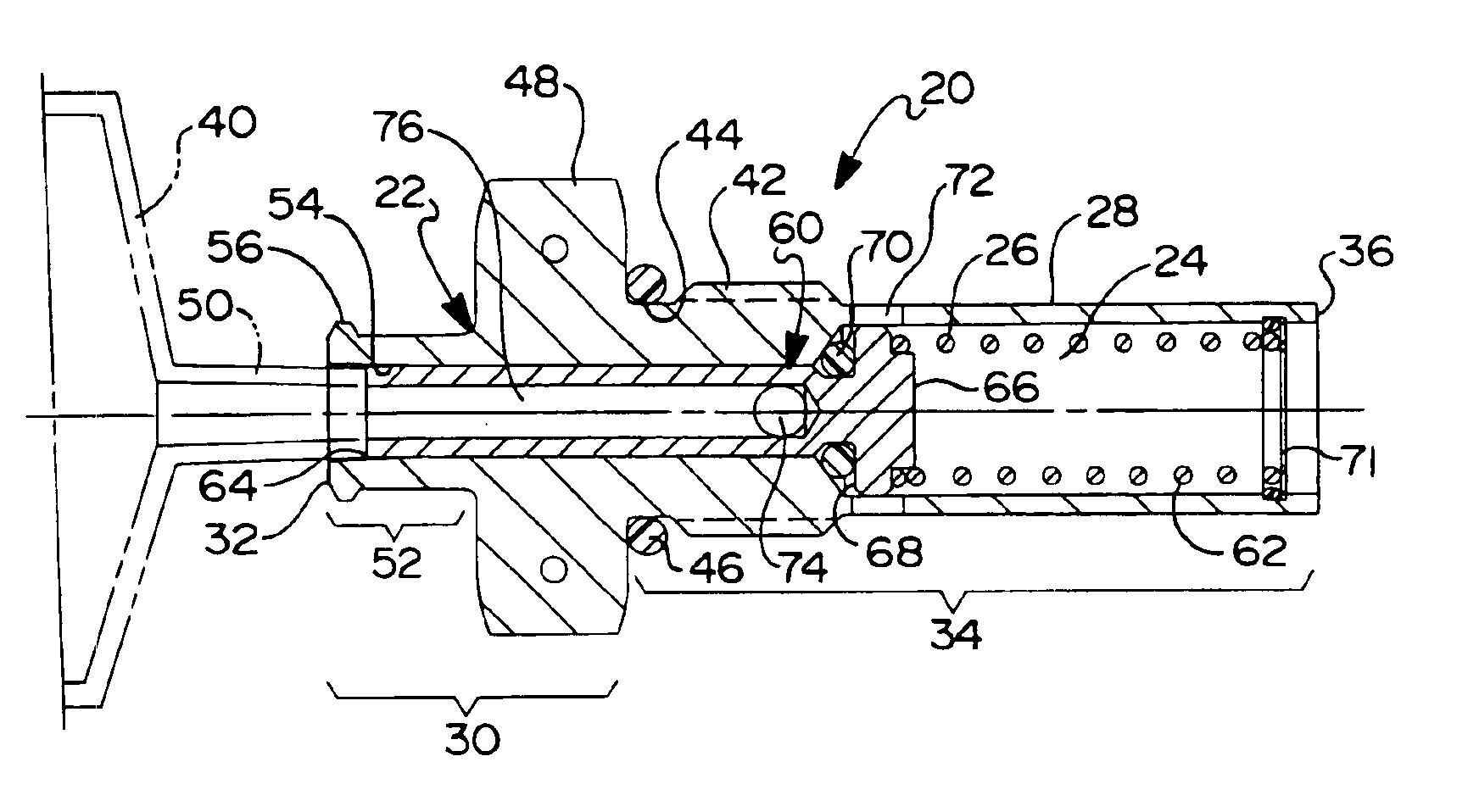
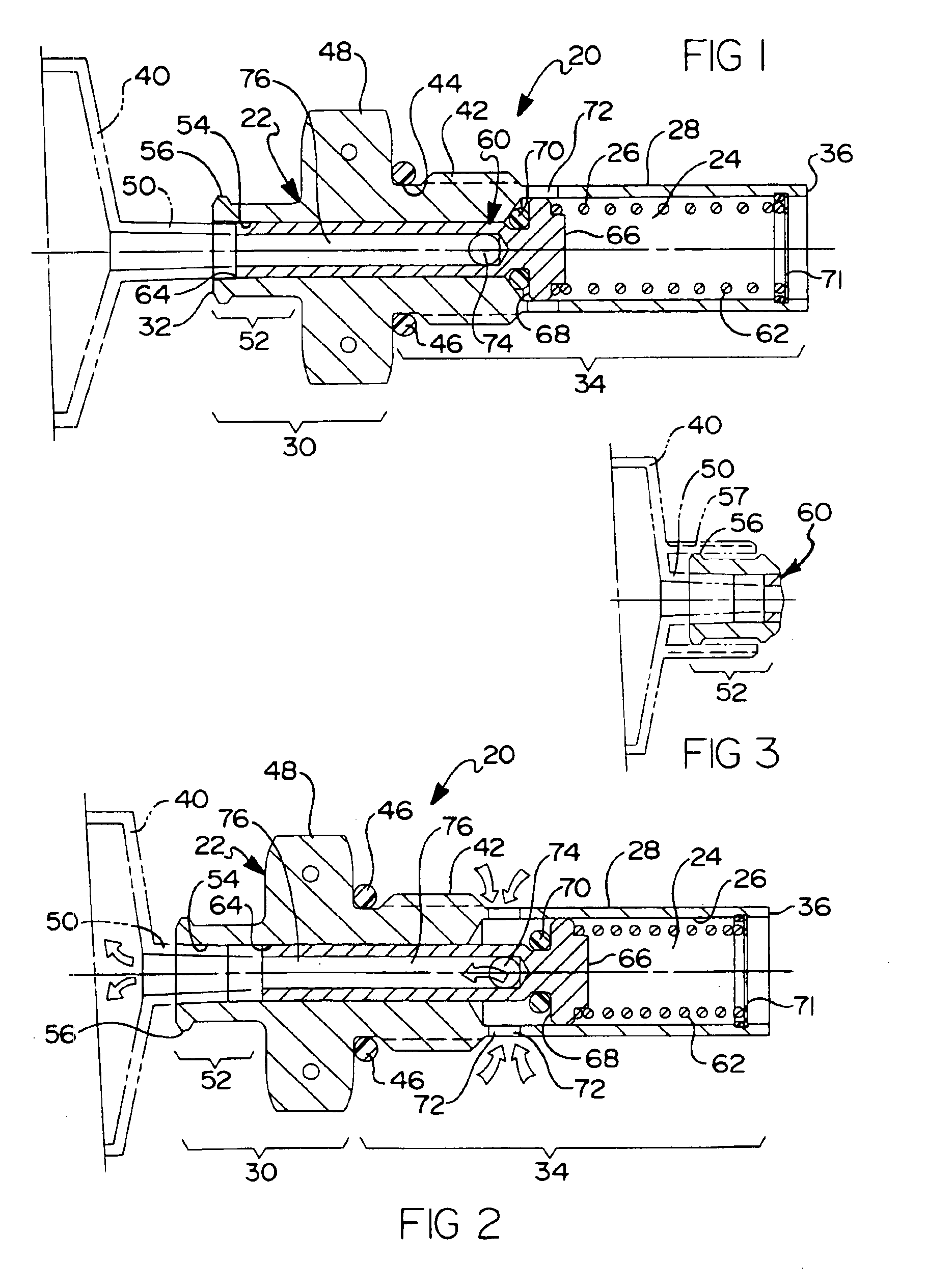
[0021]Referring now to the drawings, the preferred embodiments of the present invention are described in detail. Referring to FIG. 1, a fluid sampling valve 20 is provided that includes a generally cylindrically-shaped metal body 22 having a central longitudinal channel 24 and inner and outer surfaces 26 and 28, respectively. Body 22 further includes an external segment 30 having an external end 32 and an internal segment 34 having an internal end 36. Central longitudinal channel 24 of body 22 extends from external end 32 to internal end 36. Internal segment 34 is configured for receipt within a port of a fluid source (none shown), such as an aircraft fuel tank. The inner surface of the port preferably includes a means for securing valve 20 to the fluid source, such as an industry standard threaded surface. When securely and sealingly retained within the port of the fluid source, valve 20 may be engaged by a fluid sampling device 40, as will be described in further detail below, to ...


PUM


Abstract

A valve for connecting a fluid sampling device to a fluid source is provided that includes a body adapted to be secured to the fluid source and a valve member moveably disposed within the body. The body includes a coupling interface configured to sealingly mate with the sampling device. The valve member is actuated by the sampling device during attachment of the sampling device to the valve body. The sampling device actuated valve member is moveable between a first position in which a flow path between the fluid source and the sampling device is closed and a second position in which the flow path between the fluid source and the sampling device is open. When the fluid flow path is open, the sampling device can withdraw a fluid sample for inspection and return the fluid sample to the fluid source without exposing the fluid to the surrounding environment.

Description

FIELD OF THE INVENTION[0001]The present invention relates generally to a fluid sampling valve and more particularly to a fluid sampling valve suitable for use with a fluid sampling device, such as a syringe, to sample fluid from a fluid source.BACKGROUND OF THE INVENTION[0002]In many situations, it may be desirable to sample fluid from a fluid source without exposing the fluid to the surrounding environment. For example, during pre-flight inspections of their aircraft, pilots are required to visually inspect the fuel within the fuel system for the correct octane rating and for the presence of water and other visual contamination. Aircraft manufacturers typically install fuel drain valves at appropriate locations within an aircraft's fuel system. These drain valves are generally located on the bottom side of the aircraft's wings, fuselage and fuel filter, particularly at the lowest point within these locations.[0003]Known drain valves require a cup or bottle to catch the fuel flowing...

Claims


Application Information

Patent Timeline
Patent Type & Authority Patents(United States)
IPC IPC(8): F16L37/28F16L37/42
CPCF16L37/42
Inventor MAIVILLE, RANDOLPH L.FLYNN, WILLIAM T.
Owner EATON INTELLIGENT POWER LIMITED
Why Eureka
Try Eureka