Method of detecting a change in the structure of a complex shape article

Inactive Publication Date: 2005-05-31
ROLLS ROYCE PLC
View PDF6 Cites 2 Cited by
  • Summary
  • Abstract
  • Description
  • Claims
  • Application Information

AI Technical Summary

Benefits of technology

[0006]Accordingly the present invention seeks to provide a novel method of detecting a change in the s

Problems solved by technology

A problem with this turbine rotor is that if the turbine discs are not clamped, or fastened, together sufficiently tightly there is a significant axial gap between the axially extending sealing members and this allows the turbine rotor and hence the gas turbine engine to

Method used


Image

  • Method of detecting a change in the structure of a complex shape article
  • Method of detecting a change in the structure of a complex shape article
  • Method of detecting a change in the structure of a complex shape article

Examples


Embodiment Construction

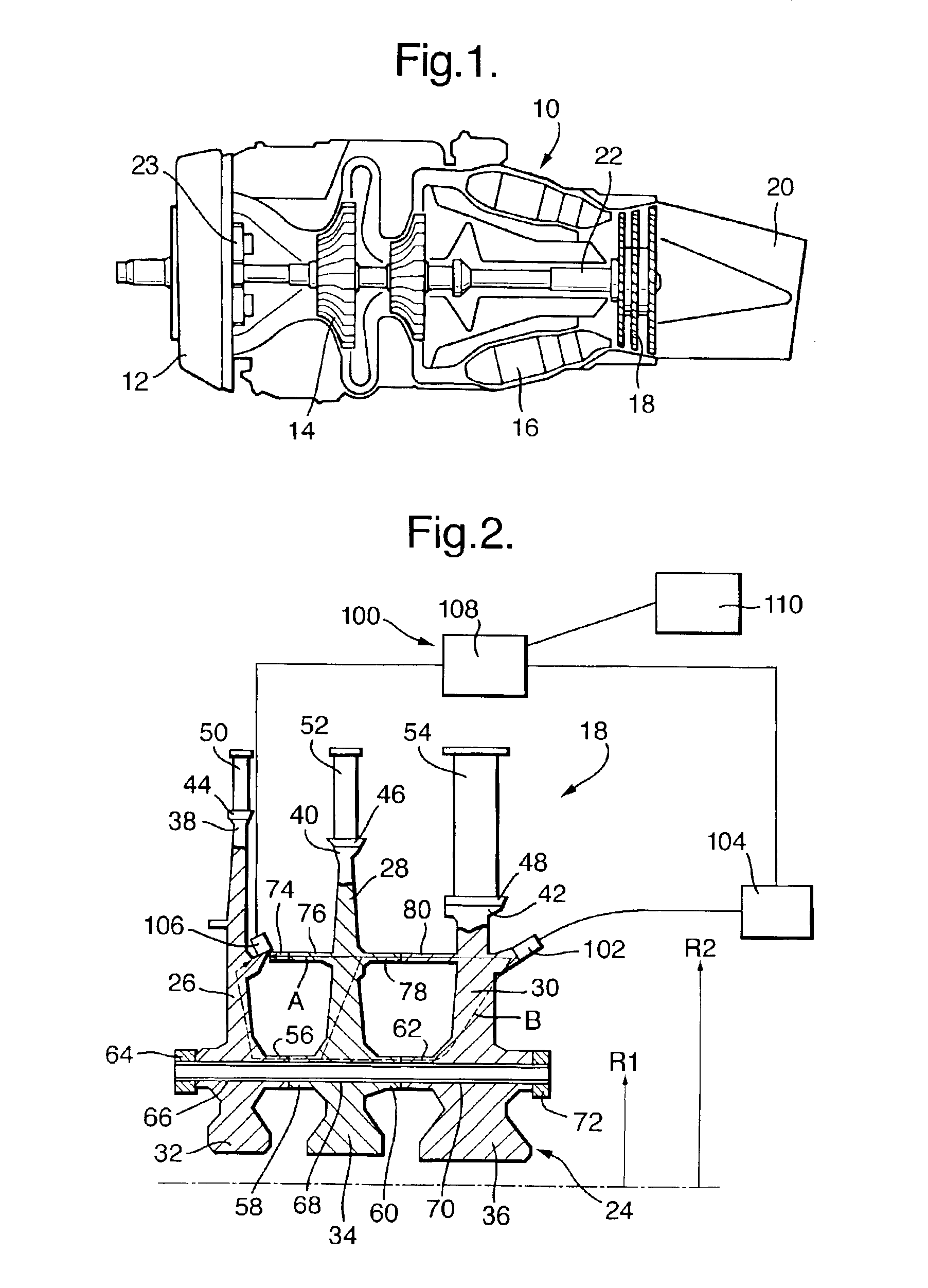
[0028]A turboprop gas turbine engine 10, as shown in FIG. 1, comprises an intake 12, a compressor section 14, a combustion section 16, a turbine section 18 and an exhaust 20. The turbine section 18 is arranged to drive the compressor section 14 via a shaft 22 and the turbine section 18 is arranged to drive a propeller (not shown) via the shaft 22 and a gearbox 23. The operation of the gas turbine engine 10 is quite conventional and will not be discussed further.

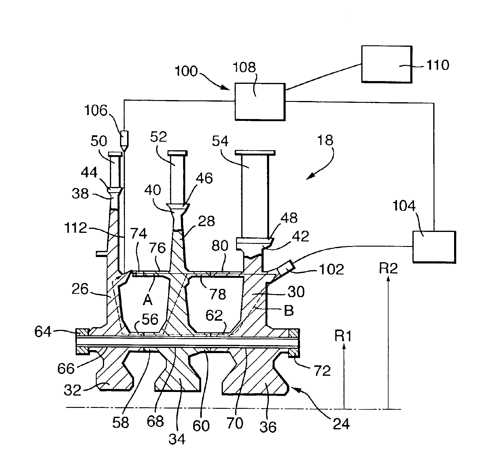
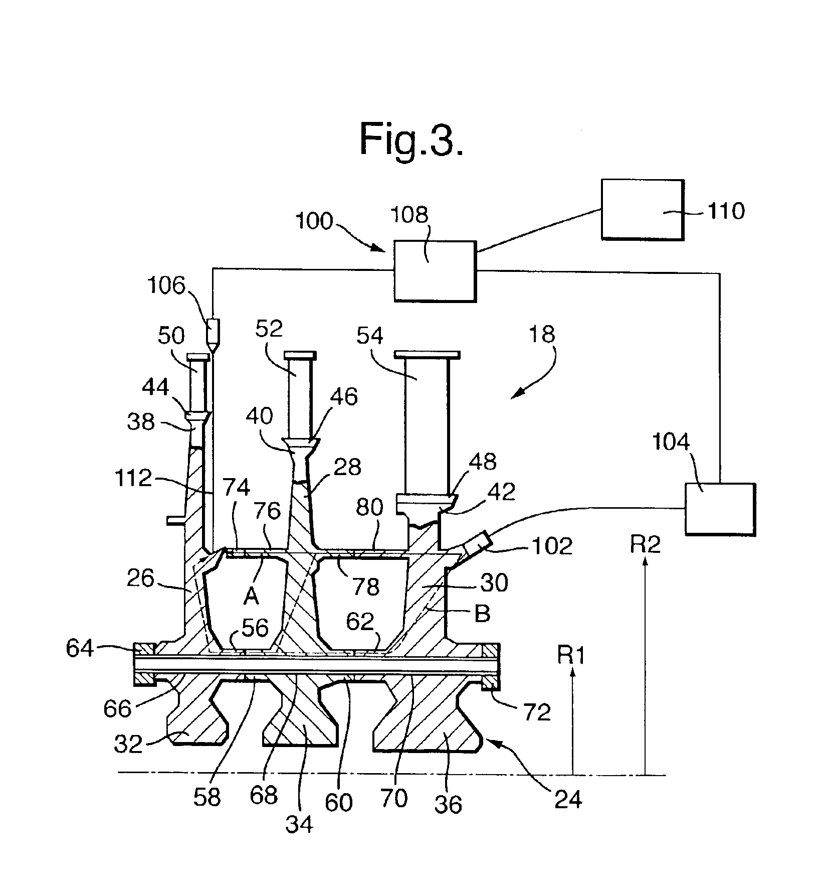
[0029]The turbine section 18, as shown more clearly in FIG. 2, comprises a turbine rotor 24, which comprises a plurality of, in this example three, axially spaced turbine discs 26, 28 and 30. The turbine discs 26, 28 and 30 have cobs 32, 34 and 36 respectively at their radially inner ends and rims 38, 40 and 42 respectively at their radially outer ends. The rims 38, 40 and 42 are provided with a plurality of circumferentially spaced axially extending slots 44, 46 and 48 respectively to receive a plurality of turbine blades 50...


PUM


Abstract

A method of detecting the change in the structure of a turbine rotor uses the steps of injecting an ultrasonic signal into the turbine rotor at a first position using a first ultrasonic transducer to produce a diffuse field ultrasonic signal in the rotor; detecting the signal in the rotor at a second position using a second ultrasonic transducer measuring the time for the signal to travel from the first ultrasonic transducer to the second ultrasonic transducer and comparing the measured time for the diffuse field ultrasonic signal to travel from the first ultrasonic transducer to the second ultrasonic transducer with a stored time for the diffuse field ultrasonic signal to travel from the first ultrasonic transducer to the second ultrasonic transducer to determine if there is a change in the structure of the turbine rotor.

Description

FIELD OF THE INVENTION[0001]The present invention relates to a method of detecting a change in the structure of a complex shape article. The present invention relates in particular to a method of detecting a change in the structure of a rotor, in particular the structure of a turbine rotor.BACKGROUND OF THE INVENTION[0002]In some gas turbine engines a turbine rotor comprises a plurality of axially spaced turbine discs. The turbine discs are fastened together at a first radially inner position by a plurality of axially extending bolts, which extend through axially extending projections on the turbine discs, and associated nuts. The turbine discs have axially extending sealing members to define seals at a second radially outer position.[0003]A problem with this turbine rotor is that if the turbine discs are not clamped, or fastened, together sufficiently tightly there is a significant axial gap between the axially extending sealing members and this allows the turbine rotor and hence t...

Claims


Application Information

Patent Timeline
IPC IPC(8): G01N29/44G01N29/07G01N29/04F01B25/26F01D21/04
CPCG01N29/07G01N29/4427G01N29/4436G01N2291/2693G01N2291/048G01N2291/102G01N2291/2638G01N2291/011
Inventor BATES, JONATHAN GWEBSTER, JOHN R
Owner ROLLS ROYCE PLC
Why Eureka
Try Eureka