Devices and methods for performing avascular anastomosis

a technology of avascular anastomosis and avascular anastomosis, which is applied in the direction of surgical staples, prostheses, veterinary instruments, etc., can solve the problems of not always achieving a leak-free seal, requiring much skill and practice on the part, and time-consuming and difficult task of suturing the anastomoses, so as to reduce the amount of manual manipulation and improve the anastomosis procedure , the effect of rapid

Inactive Publication Date: 2005-05-31
HEARTPORT
View PDF175 Cites 142 Cited by
  • Summary
  • Abstract
  • Description
  • Claims
  • Application Information

AI Technical Summary

Benefits of technology

[0014]A first aspect of the present invention takes the form of a vascular anastomosis staple device which may be used as part of an overall anastomosis stapling system and method designed to efficiently and reliably perform an end-to-side anastomosis between a graft vessel and the wall of a target vessel. The anastomosis staple device forms an atraumatic attachment to the end of the graft vessel so that only a smooth uninterrupted layer of intimal cells is exposed at the anastomosis site or within the graft vessel lumen. The anastomosis staple device creates a firm, reliable attachment between the graft vessel and the target vessel wall, with a tailored amount of tissue compression applied at the anastomosis site to form a leak-proof joint between the graft vessel and the target vessel wall. The anastomosis stapling system is designed to combine the various functions of graft vessel preparation, target vessel preparation, vessel approximation and anastomosis stapling into an integrated system of instruments so that the anastomosis can be performed efficiently with a minimum of manual manipulation of the vessels or the instruments involved. Different embodiments of the anastomosis stapling system are provided to meet the needs of performing either a first anastomosis or a second anastomosis of a bypass procedure. The anastomosis stapling system is configured to be adaptable for closed-chest or port-access CABG surgery or for more conventional open-chest CABG surgery.
[0016]A second aspect of the present invention takes the form of an anastomotic fitting for attaching the end of a graft vessel to an opening formed in the side wall of a target vessel. The anastomotic fitting has an inner flange, which provides an atraumatic attachment for the everted end of a graft vessel. The inner flange is configured so that, wherever possible, a smooth, continuous, uninterrupted layer of intimal tissue lines the graft vessel, the target vessel and the anastomotic site, with as little foreign material as possible exposed to the blood flow path. The outer flange contacts the exterior surface of the target vessel. A locking means, which may be part of the outer flange, locks the outer flange in a fixed position relative to the inner flange. The inner flange, in combination with the outer flange, provides a firm attachment to the target vessel wall. A tailored amount of compression applied by the inner and outer flanges grips the target vessel wall and creates a leak-proof seal between the graft vessel and, the target vessel. Optionally, attachment spikes on the surfaces of either the inner or the outer flange provide additional grip on the graft vessel and / or the target vessel. The attachment spikes are isolated from the blood flow lumens of the graft vessel and the target vessel so that they do not compromise the anastomotic seal or the structural integrity of the anastomotic attachment.
[0019]A second representative embodiment of the anastomotic fitting has an expanding inner flange which facilitates the atraumatic attachment of the graft vessel to the fitting and makes it easier to pass the inner flange and the everted graft vessel through the opening in the target vessel wall. The graft vessel is passed through an internal lumen of an inner sleeve which has the expandable inner flange attached at its distal end. The end of the graft vessel is everted over the unexpanded inner flange. The inner flange and the everted end of the graft vessel are passed through the opening in the target vessel wall. Once the inner flange of the fitting is in the lumen of the target vessel, it is expanded to a diameter, which is significantly larger than the opening in the target vessel wall. Then an outer flange is applied and locked into a selected position on the inner sleeve as described above to complete the anastomosis.
[0021]A second variant of the expanding inner flange has a slotted inner sleeve with multiple fingers that are oriented essentially longitudinally to the inner sleeve. Each of the fingers has a bend in it to predispose it to bend outward at the middle when under longitudinal compression. A tubular forming tool slidably received within the slotted sleeve is crenellated with multiple radially extending tabs. The radially extending tabs engage the distal ends of the fingers of the slotted inner sleeve. The anastomosis is performed by passing the graft vessel through the internal lumen of the fitting and everting it over the fingers. If desired a loop of suture can be used to hold the everted vessel in place. The fingers of the fitting and the everted end of the graft vessel are inserted through an opening in the target vessel wall. When the tubular forming tool is slid proximally with respect to the slotted inner sleeve, the radially extending tabs bear against the distal ends of the fingers, compressing them longitudinally. The fingers bow outward, folding at the bend to expand and create an inner flange, which engages the inner surface of the target vessel wall. In a preferred embodiment of this variation, the slotted inner sleeve has a proximal collar, which captures the outer flange of the fitting so that the outer flange is applied simultaneously with the expansion of the inner flange. After the inner flange has been expanded, the tubular forming tool can be removed by rotating it with respect to the slotted inner sleeve so that the tabs align with the slots allowing it to be withdrawn from the fitting. This reduces the mass of foreign material that is left as an implant at the anastomotic site.
[0024]A third approach to expediting and improving anastomosis procedures used by the present invention combines the advantages of surgical stapling technology with other advantages of anastomotic fittings. Surgical stapling technology has the potential to improve anastomosis procedures over hand suturing techniques by decreasing the difficulty and complexity of the manipulations necessary and by increasing the speed and reliability of creating the anastomosis. The Kaster vascular staple in U.S. Pat. No. 5,234,447 overcomes one of the major limitations of the previous Kolesov stapling device by allowing a stapled end-to-side anastomosis. This device, however, requires many delicate manual manipulations of the graft vessel and the staple while performing the anastomosis. This device therefore does not take full advantage of the time saving potential usually associated with stapling techniques. The present invention attempts to marry the advantages of stapling approaches and anastomotic fitting approaches while carefully avoiding their potential drawbacks. As such, the present invention takes full advantage of the speed and reliability of stapling techniques, avoiding inasmuch as possible the need for complex manual manipulations. The invention also profits from the advantages of anastomotic fittings by providing a ring or flange that exerts even pressure around the anastomotic interface to eliminate potential leaks between the stapled attachments. The ring or flange also serves as a stent or support for the anastomosis site to prevent acute or long-term closure of the anastomosis. Inasmuch as possible the bulk is of the fitting is kept on the exterior of the anastomosis so as to eliminate exposed foreign material in the bloodstream of the graft vessel or the target vessel. In most cases, only the narrow staple legs penetrate the anastomosis site. so that an absolute minimum of foreign material is exposed to the blood flow path, on the same order as the mass of suture exposed in a standard sutured anastomosis. The attachment technique for the anastomosis device eliminates the need to evert the graft vessel over a complex, irregular or sharp object such as the sharpened ends of the staple legs. Instead, a smooth ring or flange surface is provided for everting the graft vessel without damage or undue complication. The staple legs are separate or recessed within the flange to avoid potential damage to the graft vessel while attaching it to the device.
[0025]In a third aspect, the present invention takes the form of an anastomosis device, which has a ring or flange to which the graft vessel attaches, typically by everting the graft vessel over the distal end of the ring. The ring or flange resides on the exterior of the graft vessel so that it does not contact the blood flow path. A plurality of staple-like members attach the ring and the everted end of the graft vessel to the wall of the target vessel, which may be the aorta, a coronary artery or other vessel. An opening is created in the target vessel wall with an aortic punch or similar instrument to allow the target vessel lumen to communicate with the graft vessel lumen. The opening in the target vessel wall can be made before or after the device has been attached, depending on the application technique employed. In most of the examples disclosed, the staple members pierce the everted wall of the graft vessel and the wall of the target vessel to hold the two vessels together. Alternatively, the staple members may enter the lumen of the target vessel through the opening in the wall and then pierce the wall of the target vessel in the reverse direction. This variation pins together the vascular layers in the target vessel at the cut edge, potentially reducing the incidence of hemodynamically generated dissections in the wall of the target vessel.

Problems solved by technology

Suturing the anastomoses is a time-consuming and difficult task, requiring much skill and practice on the part of the surgeon.
A completely leak-free seal is not always achieved on the very first try.
CPB, circulatory isolation and cardiac arrest arc inherently very traumatic, and it has been found that the frequency of certain post-surgical complications varies directly with the duration for which the heart is under cardioplegic arrest (frequently referred to as the “crossclamp time”).
Secondly, because of the high cost of cardiac operating room time, any prolongation of the surgical procedure can significantly increase the cost of the bypass operation to the hospital and to the patient.
This requires even greater manual skill than the already difficult procedure of suturing anastomoses during open-chest CABG surgery.
These instruments unfortunately, are not easily adaptable for use in creating vascular anastomoses.
This is partially due to the difficulty in miniaturizing the instruments to make them suitable for smaller organs such as blood vessels.
However, in vascular surgery this geometry is unacceptable for several reasons.
Firstly, the inverted vessel walls would cause a disruption in the blood flow.
This could cause decreased flow and ischemia downstream of the disruption, or worse yet, the flow disruption or eddies created could become a locus for thrombosis which could shed emboli or occlude the vessel at the anastomosis site.
Secondly, unlike the intestinal tract, the outer surfaces of the blood vessels (the adventitia) will not grow together when approximated.
Because the device could only perform end-to-end anastomoses, the coronary artery first had to be severed and dissected from the surrounding myocardium, and the exposed end evened for attachment.
This technique limited the indications of the device to cases where the coronary artery was totally occluded, and therefore there was no loss of blood flow by completely severing the coronary artery downstream of the blockage to make the anastomosis.
Consequently, this device is not applicable where the coronary artery is only partially occluded and is not at all applicable to making the proximal side-to-end anastomosis between a bypass graft and the aorta.
However, this device falls short of fulfilling the desired objectives of the present invention.
Specifically, Kaster does not provide a complete system for quickly and automatically performing an anastomosis.
One of the more difficult maneuvers in applying the Kaster staple involves carefully everting the graft vessel over the sharpened ends of the staple legs, then piercing the everted edge of the vessel with the staple legs.
Experimental attempts to apply this technique have proven to be very problematic because of difficulty in manipulating the graft vessel and the potential for damage to the graft vessel wall.
Once the distal tines of the staple have been deformed, it may be difficult to insert the staple through the aortotomy opening.
Another disadvantage of the Kaster device is that the distal tines of the staple pierce the wall of the graft vessel at the point where it is everted over the staple.
Piercing the wall of the graft vessel potentially invites leaking of the anastomosis and may compromise the structural integrity of the graft vessel wall, serving as a locus for a dissection or even a tear which could lead to catastrophic failure.
Because the Kaster staple legs only apply pressure to the anastomosis at selected points, there is a potential for leaks between the staple legs.
There is also the potential that exposure of the medial layers of the graft vessel where the staple pierces the wall could be a site for the onset of intimal hyperplasia, which would compromise the long-term patency of the graft.
Firstly, the anastomotic fittings described expose the foreign material of the anastomotic device to the blood flow path within the arteries.
This is undesirable because foreign materials within the blood flow path can have a tendency to cause hemolysis, platelet deposition and thrombosis.
The anastomotic fitting described by Kaster in the '819 patent also has the potential drawback that the spikes that hold the graft vessel onto the anastomotic fitting are very close to the blood flow path, potentially causing trauma to the blood vessel that could lead to leaks in the anastomosis or compromise of the mechanical integrity of the vessels.
However, this device is awkward for use in end-to-side anastomosis and tends to deform the target vessel; therefore it is not currently used in CABG surgery.
Due to the delicate process needed to insert the vessels into the device, it would also be unsuitable for port-access surgery.

Method used


Image

  • Devices and methods for performing avascular anastomosis
  • Devices and methods for performing avascular anastomosis
  • Devices and methods for performing avascular anastomosis

Examples


first embodiment

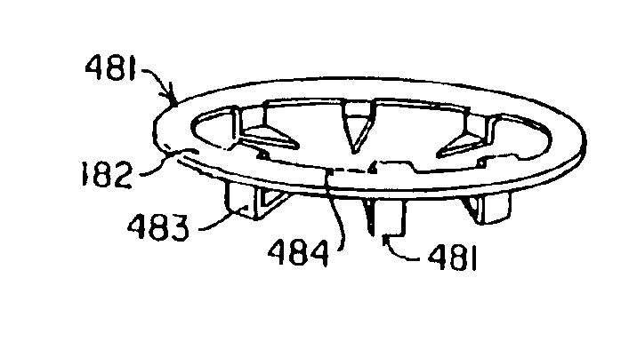
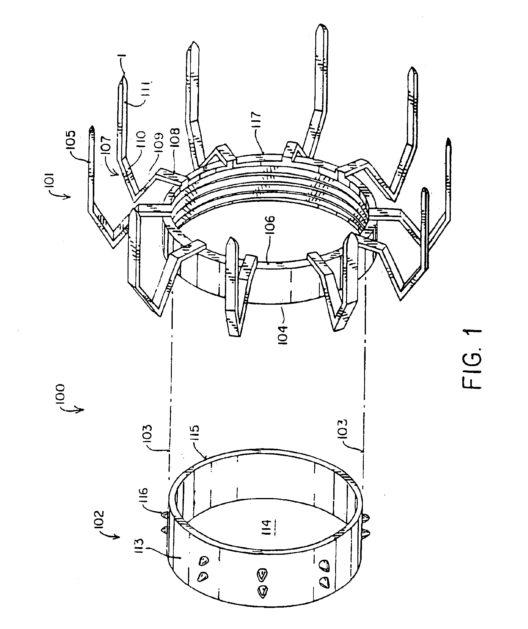
[0083]FIG. 1 is a perspective drawing of the anastomosis staple device of a first aspect of the present invention. The anastomosis staple device 100 consists of two parts: an anchor member 101, and a coupling member 102. The anchor member 101 forms the attachment to the exterior surface of the wall of a target vessel such as the aorta. The coupling member 102 forms the attachment to the bypass graft vessel. When the coupling member is joined to the anchor member, as shown by the dotted lines 103, it forms a complete anastomosis.

[0084]The anchor member 101 has a ring-shaped frame 104 which is configured to encircle an opening in the wall of a target vessel, such as the aorta. The ring-shaped frame 104 has a plurality of attachment legs 105, preferably six to twelve, circumferentially spaced around the frame 104 and projecting from the distal end 106 of the ring. The anchor member 101 is preferably made of stainless steel or a titanium alloy for strength, biocompatibility and absence ...

second embodiment

[0102]FIG. 7A shows a perspective drawing of the graft insertion tool 122 for use in performing the second anastomosis on a graft vessel, one end of which has already been anastomosed, or for other situations when both ends of the graft vessel are not available, such as when making the distal anastomosis on an internal mammary artery bypass graft. This embodiment of the graft insertion tool 122 is made with a two-part, hinged holder 154 for the coupling member of the anastomosis staple device so that the holder 154 can be removed from around the graft vessel 148 after both ends of the graft have been anastomosed. The holder 154 is attached to the distal end of a tubular member 155 which is attached on its proximal end to a handle grip 156. A shaft 157 is slidably received within the tubular member 156. The distal end of the shaft 157 is attached to a U-shaped yoke 158 which is configured to grip a flange 159 or a pair of lugs on the proximal end of the anchor member 101. The handle ...


PUM


Abstract

A system for performing an end-to-side vascular anastomosis, including an anastomosis device, an application instrument and methods for performing a vascular anastomosis. The system is applicable for performing an anastomosis between a vascular graft and the ascending aorta in coronary artery bypass surgery, particularly in port-access CABG surgery. A first aspect of the invention includes a vascular anastomosis staple. A first configuration has two parts: an anchor member, forming the attachment with the target vessel wall and a coupling member, forming the attachment with the bypass graft vessel. The anastomosis is completed by inserting the coupling member, with the graft vessel attached, into the anchor member. A second configuration combines the functions of the anchor member and the coupling member into a one-piece anastomosis staple. A second aspect of the invention includes an anastomotic fitting, having an inner flange over which the graft vessel is everted and an outer flange which contacts the exterior surface of the target vessel. A tailored amount of compression applied by the inner and outer flanges grips the target vessel wall and creates a leak-proof seal between the graft vessel and the target vessel. A third aspect of the invention has a flange to which the graft vessel attaches, by everting the graft vessel over the flange, and a plurality of staple-like members which attach the flange and the everted end of the graft vessel to the wall of the target vessel to form the anastomosis

Description

CROSS-REFERENCE TO RELATED APPLICATIONS[0001]This application is a continuation of U.S. patent application No. 10 / 339,434, filed Jan. 9, 2003, which is a continuation of U.S. patent application No. 10 / 177,371, filed Jun. 20, 2002, now issued as U.S. Pat. No. 6,699,257, which is a continuation of U.S. patent application Ser. No. 09 / 966,118, filed Sep. 28, 2001, now issued as U.S. Pat. No. 6,451,034, which is a continuation of U.S. patent application Ser. No. 09 / 756,355, filed Jan. 8, 2001, now issued as U.S. Pat. No. 6,443,965, which is a continuation of U.S. patent application Ser. No. 09 / 315,365, filed May 18, 1999, now U.S. Pat. No. 6,171,321, which is a continuation of application Ser. No. 09 / 166,338, filed Oct. 5, 1998, now issued as U.S. Pat. No. 5,904,697, which is a divisional of Ser. No. 08 / 789,327, filed Jan. 23, 1997, now issued as U.S. Pat. No. 5,817,113, which is a divisional of application Ser. No. 08 / 394,333, filed Feb. 24, 1995, now issued as U.S. Pat. No. 5,695,504. ...

Claims


Application Information

Patent Timeline
Patent Type & Authority Patents(United States)
IPC IPC(8): A61B17/115A61B17/03A61B17/064A61B17/11A61B17/12A61F2/00A61B17/00
CPCA61B17/064A61B17/115A61B17/12036A61B17/12045A61B17/12136A61B17/12109A61B17/0643A61B17/11A61F2210/0014A61B2017/00243A61B2017/0641A61B2017/1135A61B2017/12127A61F2002/30092
Inventor GIFFORD, III, HANSON S.BOLDUC, LEE R.STEIN, JEFFREY A.DICESARE, PAUL C.COSTA, PETER F.HOLMES, WILLIAM A.
Owner HEARTPORT
Why Eureka
Try Eureka