
Method of detecting flicker, and video camera using the method

Inactive Publication Date: 2005-05-31
STMICROELECTRONICS SRL
View PDF10 Cites 23 Cited by
  • Summary
  • Abstract
  • Description
  • Claims
  • Application Information

AI Technical Summary

Benefits of technology

[0008]An object of the present invention is to provide a time-domain technique for detecting and reducing the frequency of flicker for motion video cameras, and which is also capable of being applied to both full-field exposure sensors and rolling-window exposure sensors.

Problems solved by technology

The problem is most apparent at low exposure values.
However, the problem is compounded if camera field rates and frequency of the alternating current source differs by some amount, causing the luminance modulation bands to roll up or down the image.
Detection of lighting flicker in the spatial domain is difficult in the case of rolling-window exposure sensors, and is much more difficult in the case of full-field exposure sensors.
In the former case the difficulty is due to potential strong correlations between expected banding patterns caused by lighting flicker and variations in actual scene luminance.
U.S. Pat. No. 5,272,539 discloses a video camera with flicker detection, but in this prior arrangement the detector frame rate is coupled with the video frame rate, which limits its usefulness.

Method used


Image

  • Method of detecting flicker, and video camera using the method
  • Method of detecting flicker, and video camera using the method
  • Method of detecting flicker, and video camera using the method

Examples


Embodiment Construction

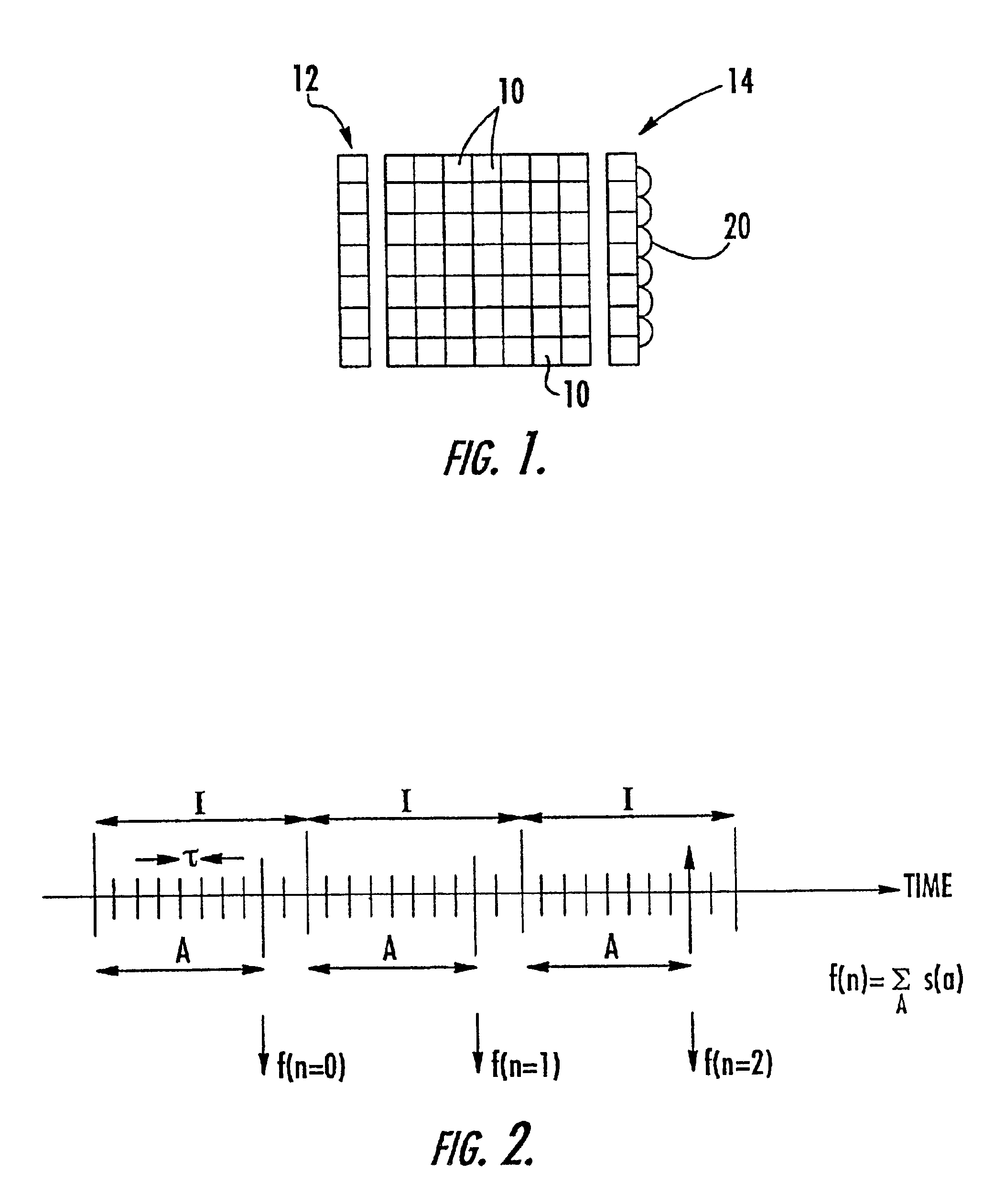
[0020]Referring to FIG. 1, a photosensitive array comprises a main array of pixels 10. It will be appreciated that FIG. 1 is highly schematic, with only a small number of pixels 10 being shown. Additionally, the photosensitive array comprises one or more (in this embodiment, two) super-pixels 12 and 14. Each of the super-pixels 12, 14 differ from the pixels 10 of the main array in two principal ways.

[0021]The super-pixels 12, 14 are physically large in comparison to the pixels 10 of the main array so that they may stand a better chance of imaging some part of the scene which contains a flickering light source or reflects such a flickering source. In this example, each super-pixel is one entire column of photosensitive pixel elements 10 which have been electrically connected in common.

[0022]The super-pixels 12, 14 are exposed and sensed in a manner independent from the pixels 10 of the main array. While each line of the main array is sensed at the frame rate dictated by each applicat...


PUM


Abstract

Lighting flicker in the output of a video imaging device is detected. The video imaging device has a main picture area divided into pixels for producing successive images at a frame rate. A series of signals are produced from at least one additional picture area adjacent the main picture area, with the additional picture area having a size substantially larger than a pixel. Each of the signals is a function of light incident on the additional picture area in a time period substantially shorter than that of the frame rate. A predetermined number of the signals are accumulated to form a series of compound samples, and the compound samples are filtered to detect components indicating the lighting flicker. The filtering is performed using a bandpass filter tuned to the nominal flicker frequency. The compound samples are formed at a sample rate which is a multiple of the nominal flicker frequency, and the filtering is performed by taking the fundamental output component of a radix-N butterfly.

Description

FIELD OF THE INVENTION[0001]The present invention relates to a method of detecting lighting induced flicker in a video signal, and to a video camera equipped for carrying out this method.BACKGROUND OF THE INVENTION[0002]Artificial lighting derived from alternating current sources, particularly fluorescent lighting, contains a strong brightness modulation component, or flicker, at twice the frequency of the alternating current sources. This factor of 2 arises from the power relation between instantaneous voltage of the alternating current sources and instantaneous brightness, and from the trigonometric relation cos2 (x=0.5(1+cos(2x)). Commonly encountered flicker frequencies are 100 Hz in Europe and 120 Hz in the United States. Although invisible to the human eye, flicker may be highly visible to image sensors. The problem is most apparent at low exposure values. An imagine sensor samples this modulation waveform as reflected from objects in the scene and reproduces it perfectly.[000...

Claims


Application Information

Patent Timeline
IPC IPC(8): H04N5/235
CPCH04N5/235H04N5/2357Y10S348/91H04N23/70H04N23/745
Inventor HENDERSON, ROBERTSMITH, STEWART GRESTYHURWITZ, JONATHAN EPHRIAM DAVIDMURRAY, ANDREW
Owner STMICROELECTRONICS SRL
Features
  • Generate Ideas
  • Intellectual Property
  • Life Sciences
  • Materials
  • Tech Scout
  • Unparalleled Data Quality
  • Higher Quality Content
  • 60% Fewer Hallucinations
Learn More