
Lubricant depletion detection in a self-healing disk drive

Inactive Publication Date: 2005-05-31
WESTERN DIGITAL TECH INC
View PDF9 Cites 11 Cited by
  • Summary
  • Abstract
  • Description
  • Claims
  • Application Information

AI Technical Summary

Benefits of technology

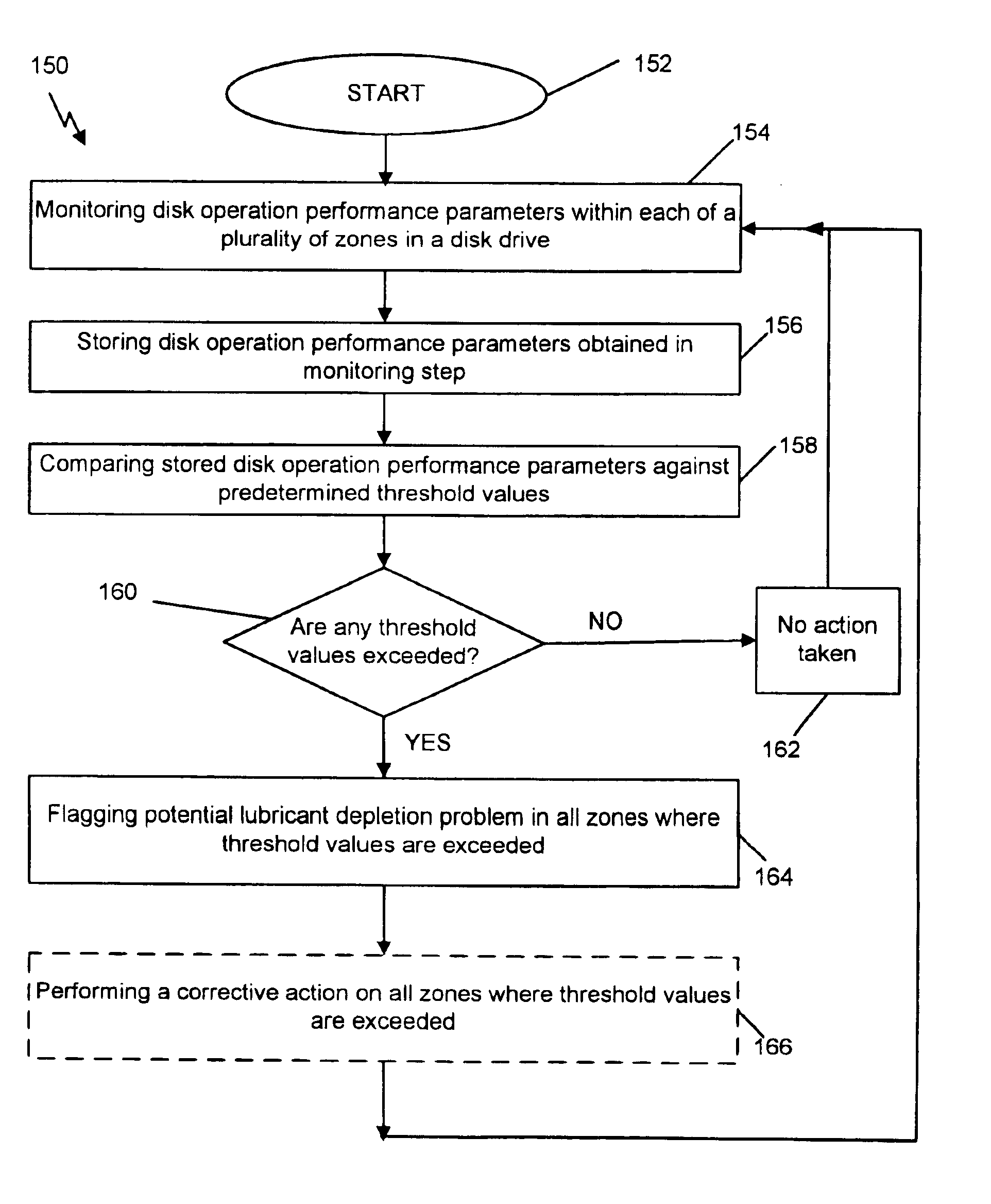
[0008]The present invention provides a method and apparatus for detecting lubricant depletion in a disk drive. Disk operation performance parameters are monitored for each of a plurality of zones on the surface of the disk, and these performance parameters are stored in a data store. Examples of performance parameters monitored for each of the zones include, but are not limited to, dwell time, head flying height changes, and data recovery procedure measurements. The stored disk operation performance parameters are then compared against predetermined threshold values. If

Problems solved by technology

If the values of the performance parameters exceed the predetermined threshold values for any of the zones, a potential lubricant depletion problem is flagged for the corresponding zone.

Method used


Image

  • Lubricant depletion detection in a self-healing disk drive
  • Lubricant depletion detection in a self-healing disk drive
  • Lubricant depletion detection in a self-healing disk drive

Examples


Embodiment Construction

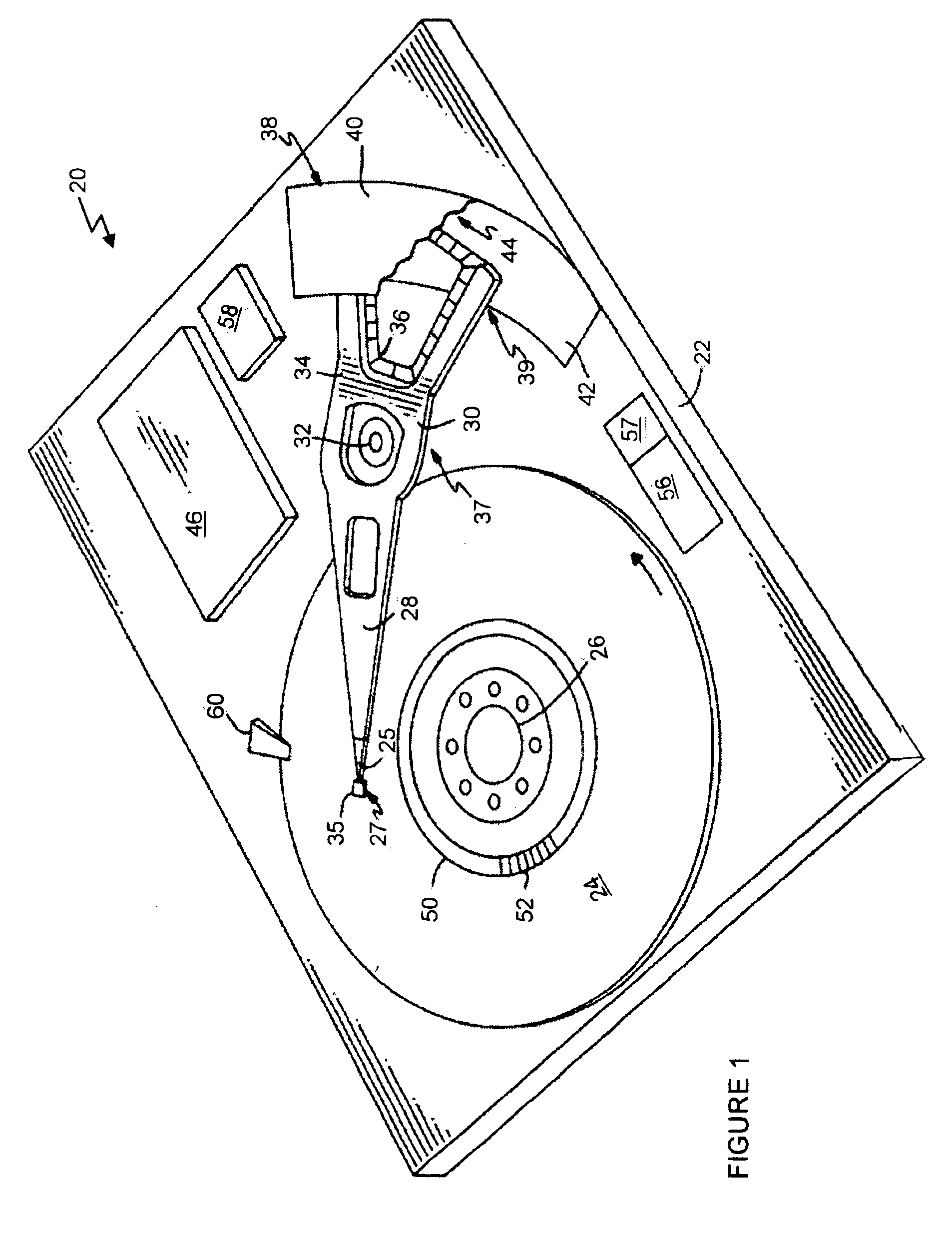
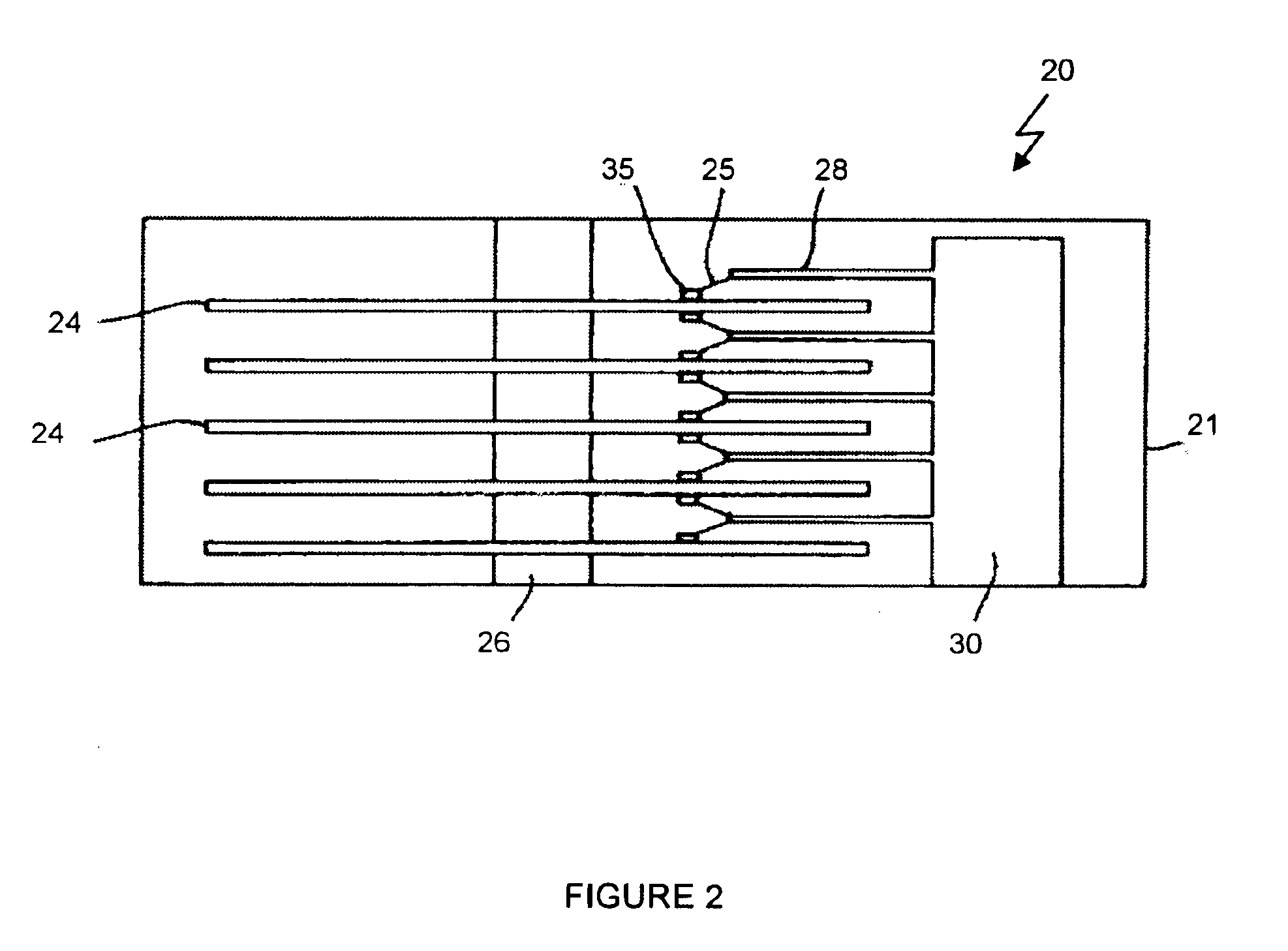
[0016]Turning to the Drawings, wherein like numbers denote like parts throughout the several views, FIGS. 1 and 2 illustrate a data storage system 20 within which the apparatus and method for detection of lubricant depletion is found. This data storage system 20, as is best shown in FIG. 2, typically includes one or more rigid data storage disks 24 which are stacked coaxially in a tandem spaced relationship, and rotate about a spindle motor 26 at a relatively high rate of rotation.

[0017]As is depicted in FIG. 1, each disk 24 is typically magnetically formatted to include a plurality of spaced concentric tracks 50. One or more of the disks 24 may alternatively be magnetically formatted to include a spiraled track configuration, or a combination of concentric and spiraled track configurations. Digital information is typically stored in the form of magnetic transitions along the tracks 50. The tracks 50 are generally divided into a number of sectors 52, with each sector 52 comprising a...


PUM


Abstract

A method and apparatus for detecting lubricant depletion in a disk drive is provided. Disk operation performance parameters are monitored for each of a plurality of zones on the surface of the disk and stored. Examples of performance parameters include dwell time, flying height changes, and data recovery measurements. The performance parameters are compared against predetermined threshold values. If the performance parameters exceed the predetermined threshold values for any of the zones, a potential lubricant depletion or other general degradation problem is flagged for the corresponding zone. Optionally, when a potential lubricant depletion problem is flagged for a particular zone, corrective action is taken. Examples of corrective action include moving recently accessed data from the flagged zone to a zone not identified as having a lubricant depletion problem, moving older archival data to the flagged zone, and / or removing access to the flagged zone.

Description

FIELD OF THE INVENTION[0001]The present invention relates generally to disk drive systems, and more specifically to an apparatus and method for detecting long-term lubricant depletion from a disk surface of a disk drive, and taking appropriate corrective action.BACKGROUND OF THE INVENTION[0002]The storage capacity of hard disk drives is increasing in rapid fashion. In fact, the capacity of an average disk drive has doubled every 18 months, and, in recent years, has even outpaced the tremendous performance advances in the integrated circuit industry. In order to maintain this explosive increase in capacity, the components that make up the drives are quickly evolving and new technologies are being developed.[0003]As storage densities increase, the distance between the read / write head and the disk surface decreases, since the signal that can be obtained from the data stored within the disk increases as the head moves closer to the disk. This evolution has progressed to the point that, ...

Claims


Application Information

Patent Timeline
IPC IPC(8): G11B33/14G11B27/36G11B25/04G11B19/04
CPCG11B19/04G11B25/043G11B33/148G11B27/36G11B2220/20
Inventor GILLIS, DONALD RAYSMITH, GORDON JAMESSMITH, MOLLY
Owner WESTERN DIGITAL TECH INC
Learn More