
Self-healing tree network

a tree network and self-healing technology, applied in the field of data communication, can solve the problems of slow network recovery process, adverse effects on network bandwidth, and inability to recover from tree network, so as to avoid the creation of network loops

Inactive Publication Date: 2007-06-19
OMNILUX
View PDF24 Cites 64 Cited by
  • Summary
  • Abstract
  • Description
  • Claims
  • Application Information

AI Technical Summary

Benefits of technology

The protocol enables rapid detection and recovery from network failures, minimizing CPU utilization and preventing network loops, ensuring continuous network connectivity and optimizing network performance by allowing nodes to self-detect isolation and re-establish connections efficiently.

Problems solved by technology

This eventually leads to the network as a whole to be saturated with broadcast packets, a situation often referred to as “broadcast storm,” such that network bandwidth is adversely affected.
A tree network, however, suffers from certain limitations.
However, upon isolation detection, network recovery in such a system is a slow process, typically requiring several minutes.

Method used


Image

  • Self-healing tree network
  • Self-healing tree network
  • Self-healing tree network

Examples


Embodiment Construction

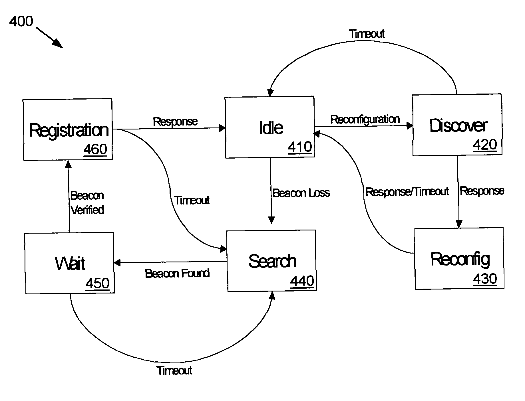
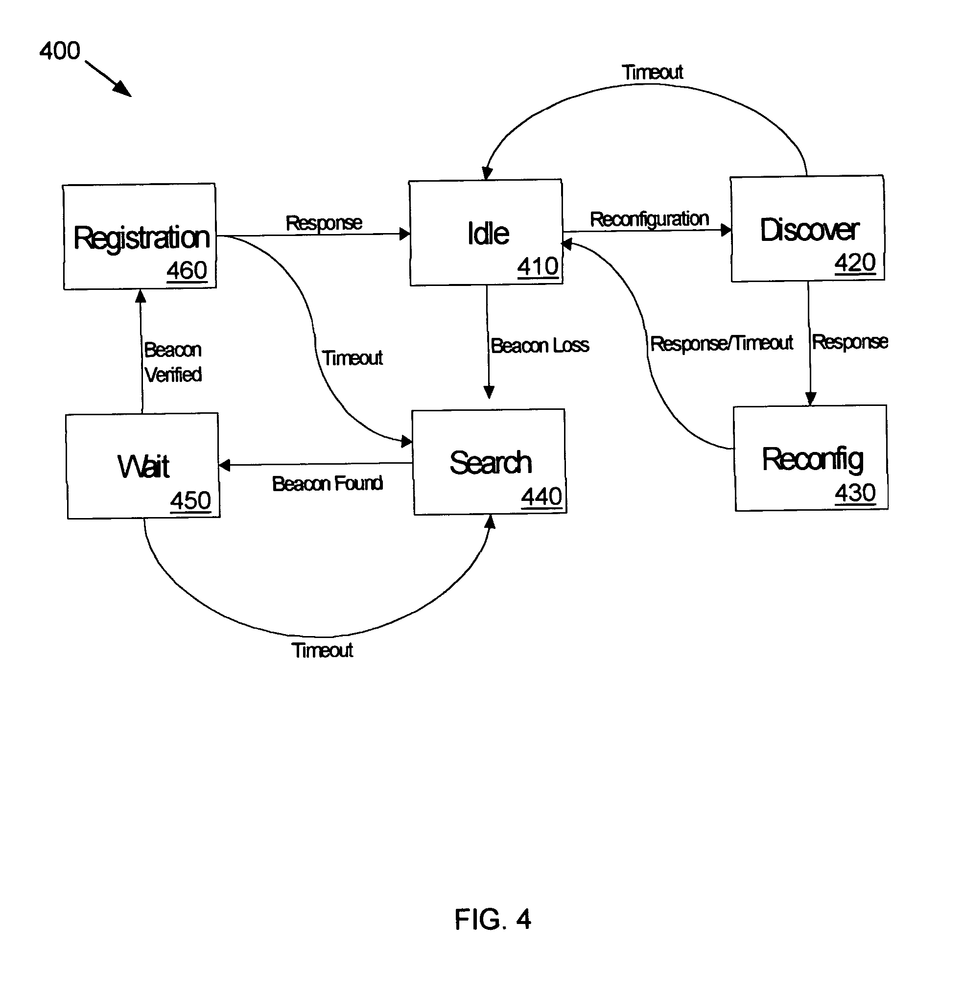
[0024]In self-healing communications networks described herein with respect to FIGS. 4–6, a number of nodes are physically deployed in a mesh configuration and may be logically connected in a tree structure. The node may provide sophisticated switch functions, such as switching decision based on the IP address or TCP port of the received packet. Such interconnected nodes can then simultaneously behave as Layer 2 (Ethernet) switches and Layer 3 (IP) switches, wherein Layer-2 switching may be provided for applications that do not need the flexibility or the additional complexities of Layer 3 switching and the Layer-3 capabilities allows for additional network flexibility. Such additional switching functionality is advantageous for provisioning advanced services, but is not required to perform the processes of the present disclosure.

[0025]The decision as to where a received packet is sent (i.e., a switching decision) is determined by each network node based on the MAC address of a rece...


PUM


Abstract

A communications network is provided with a self-healing topological architecture. Each node in the network detects continuously transmitted beacon packets that are propagated through the network at regular intervals by a root node. Upon failure to detect a new beacon packet after a predetermined time from a parent node, a network node determines a network isolation condition and searches for another node that is still actively connected in the network. Algorithms are provided for registering with and identifying active parent node candidates during a network failure so as to prevent the creation of network loops.

Description

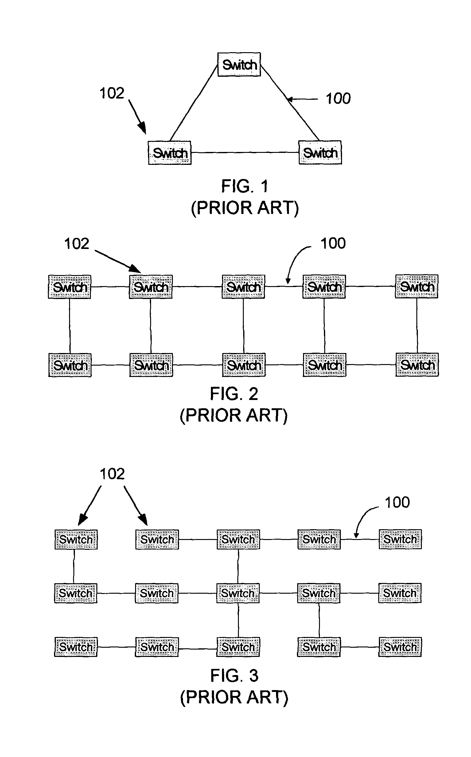
FIELD OF THE INVENTION[0001]This invention generally relates to data communication, and in particular it relates to network signaling.BACKGROUND OF THE INVENTION[0002]A communications network, such as a computer network, a telecommunications network, an optical network, a wireless network, or any other network type, typically includes a number of nodes that allow routing, signaling and communication of data between electronic, telephonic or computing devices. Many such communications networks are known to include Layer 2 (Ethernet) or Layer 3 (Internet Protocol or IP) switches to readily accomplish these functions. The Layer 2 protocol is also referred to as a Data Link layer. The main task of this Data Link layer is to configure a raw transmission line such that it remains free of transmission errors.[0003]Referring now to FIGS. 1–3, in an Ethernet-based local-area network (LAN), network nodes or switches 102 are interconnected by a plurality of network segments 100. The key functi...

Claims


Application Information

Patent Timeline
Patent Type & Authority Patents(United States)
IPC IPC(8): G06F15/173H04L69/40
CPCH04L69/40
Inventor ADHIKARI, PRASANNA
Owner OMNILUX
Learn More