Vehicle seat with a catch on one side and with a retaining device

a technology of vehicle seat and retaining device, which is applied in the direction of movable seats, roofs, pedestrian/occupant safety arrangements, etc., can solve the problem of accident-related acceleration of vehicle seat, and achieve the effect of reducing the number of accidents

Inactive Publication Date: 2005-06-07
C ROB HAMMERSTEIN GMBH & CO KG
View PDF12 Cites 62 Cited by
  • Summary
  • Abstract
  • Description
  • Claims
  • Application Information

AI Technical Summary

Benefits of technology

[0015]In a preferred development of the invention the engaging piece is configured into a substantially annular shape and entirely encloses the sector gear. Said sector gear in turn is preferably realized in a long hole, meaning it is closed on all sides.

Problems solved by technology

At that point, it is possible that an acceleration of the

Method used


Image

  • Vehicle seat with a catch on one side and with a retaining device
  • Vehicle seat with a catch on one side and with a retaining device
  • Vehicle seat with a catch on one side and with a retaining device

Examples


Embodiment Construction

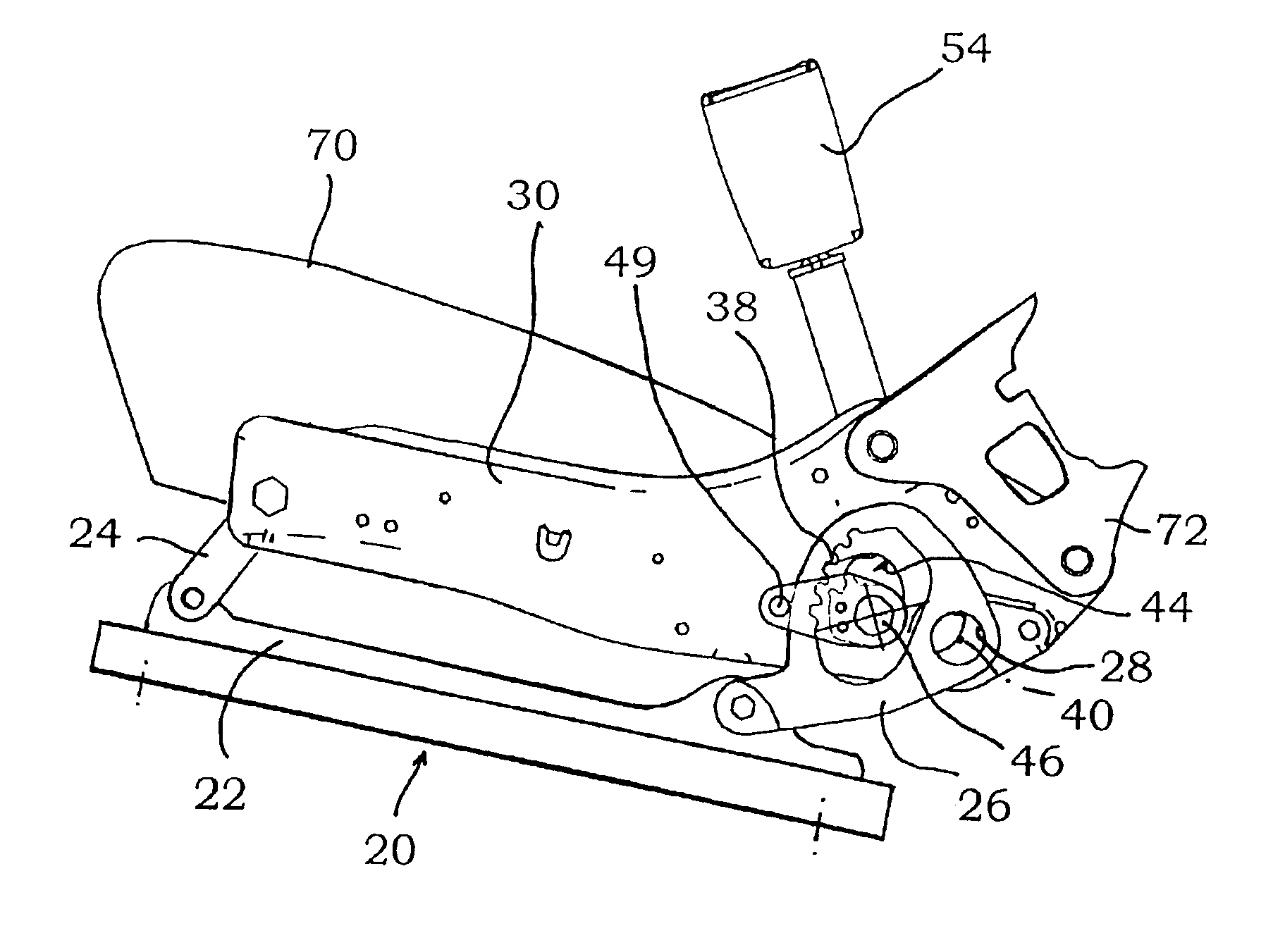
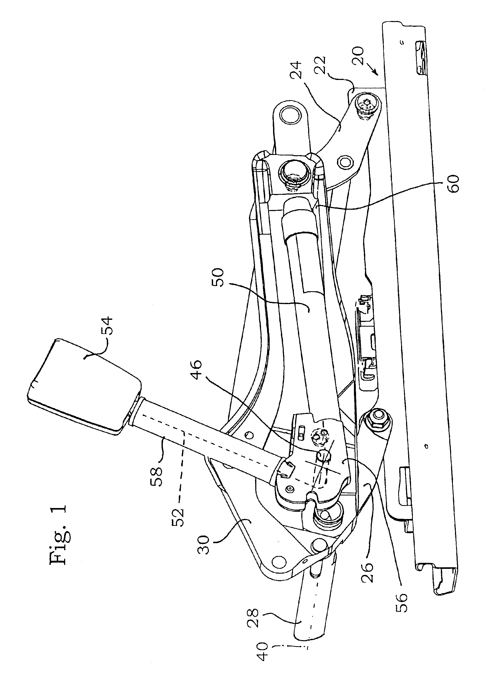
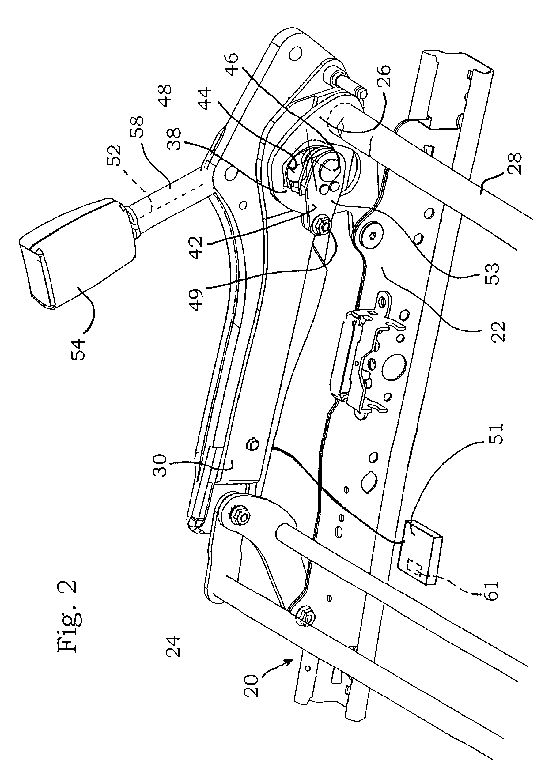
[0024]The FIGS. 1 through 5 each show only part of an underframe of a vehicle seat. The FIGS. 1, 2, 4 and 5 only show one couple of rails with a seat rail 22 and an associated bottom rail pertaining to a lengthwise adjustment device 20. Either seat rail 22 is hinge-linked to a front pivoting support 24 and to a rear oscillating crank. The FIGS. 1, 2, 4 and 5 only show the right rear oscillating cranks 26. The left rear oscillating crank is built according to substantially the same principle. They are arranged, and more specifically immobilized, in a manner well known in the art; in this connection, the reader is referred to DE 198 36 425.3.

[0025]The two rear oscillating cranks are rotationally joined together by a tie bar 28. The left rear pivoting support (not shown) is adjusted with the catch device illustrated in FIG. 3 and mentioned herein above. The right rear pivoting support is given its angular position by the tie bar 28. Thus, the right rear oscillating crank 26 is not immo...


PUM


Abstract

The motor vehicle seat of a motor vehicle comprises an underframe and a seat carrier that is height-adjustably connected to the underframe through rear oscillating cranks. A catch device is directly assigned to one of the two rear oscillating cranks. A non-rotatable tie bar joins the two rear oscillating cranks so that they are parallel when the vehicle seat is subjected to normal load. A retaining device has a sector gear firmly connected to the other one of the two rear oscillating cranks. An engaging piece which is movably disposed on the seat carrier or on the underframe, is provided with teeth devised for engagement with the sector gear and is disengaged from the sector gear as long as the vehicle seat is subjected to normal load. When the associated motor vehicle is subjected to a crash load an actuator is activated and causes the engaging piece to move into positive mesh with the sector gear. It is activated both for a positive and for a negative acceleration of the vehicle seat in the event of an accident. The teeth of the sector gear are configured in such a manner that their flanks, which are located on either side thereof, are oriented substantially radially relative to the orientation of said sector gear so that, during an accident situation, the sector gear is locked in the two directions of rotation upon engagement of the engaging piece.

Description

BACKGROUND OF THE INVENTION[0001]The invention relates to a motor vehicle seat with a) an underframe with b) a seat carrier that is height-adjustably connected to the underframe through a left rear oscillating crank and through a right rear oscillating crank, with c) a catch device which is directly assigned to one of the two rear oscillating cranks and permits to adjust and lock the angular position of said crank relative to the underframe, with d) a non-rotatable tie bar that joins the two rear oscillating cranks so that they are parallel when the vehicle seat is subjected to normal load, with e) a retaining device having a sector gear firmly connected to the other one of the two rear oscillating cranks, an engaging piece which is movably disposed on the seat carrier or on the underframe, is provided with teeth devised for engagement with the sector gear and is disengaged from the sector gear when the vehicle seat is subjected to normal load, and an actuator that is activated when...

Claims


Application Information

Patent Timeline
IPC IPC(8): B60N2/42B60N2/06B60N2/427B60N2/433B60N2/16B60N2/07
CPCB60N2/0715B60N2/1615B60N2/43B60N2/4214B60N2/42736B60N2/165
Inventor BECKER, BURCKHARDBENEKER, WILFRIED
Owner C ROB HAMMERSTEIN GMBH & CO KG
Why Eureka
Try Eureka