Dual-motion auto-stimulation device

a dual-motion, auto-stimulation technology, applied in the field of sexual devices, can solve the problems of not all sex products for sale are devices, disappointingly unsatisfactory sexually, unfavorable sexuality, and not being easily available,

a dual-motion, auto-stimulation technology, applied in the field of sexual devices, can solve the problems of not all sex products for sale are devices, disappointingly unsatisfactory sexually, unfavorable sexuality, and not being easily available,

US6902525B1Inactive Publication Date: 2005-06-07JEWELL STEPHEN W

Image

  • Dual-motion auto-stimulation device
  • Dual-motion auto-stimulation device
  • Dual-motion auto-stimulation device

Examples


Embodiment Construction

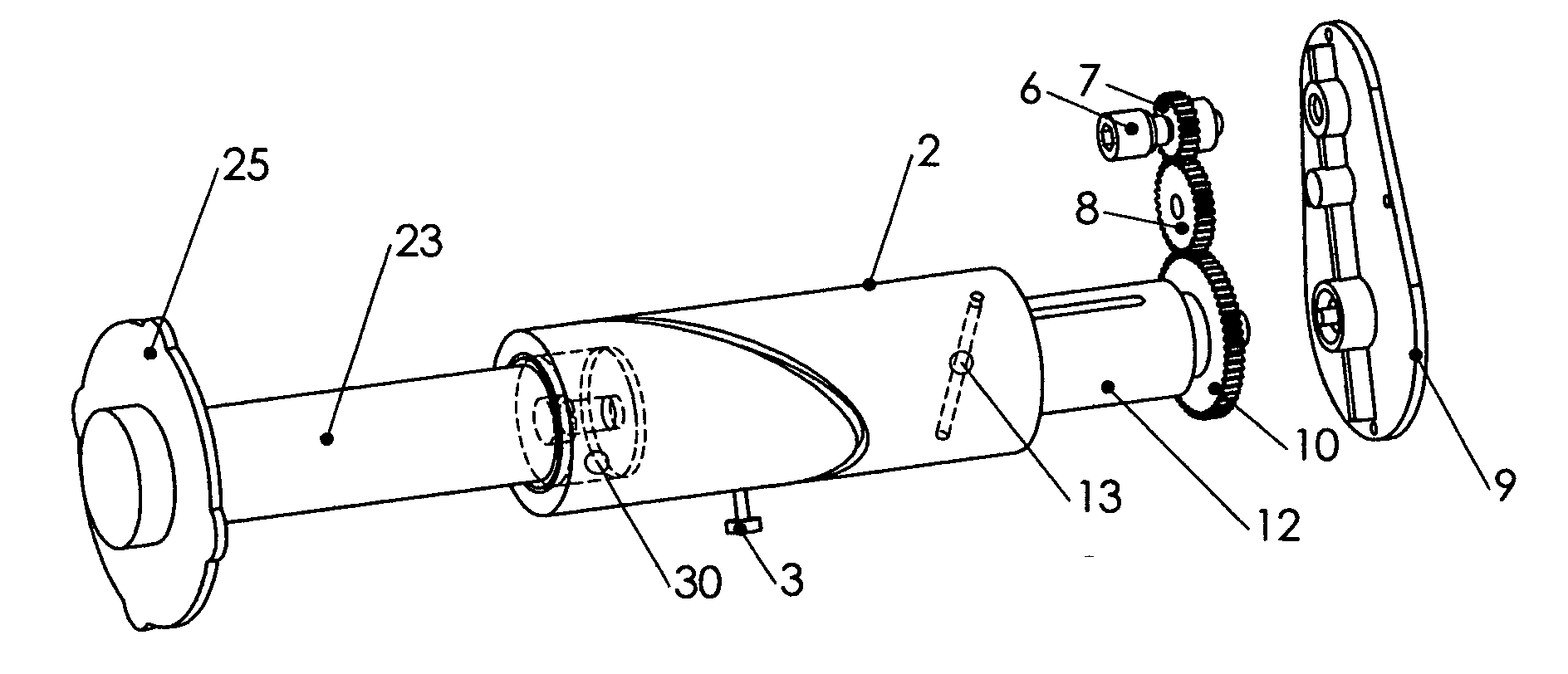
[0044]The device of the present invention is designed to take rotary power from an external power source, such as a cordless electric screwdriver or the like, and transmit that energy into both rotary and reciprocating linear activation of sexual devices used by both males and females for the purpose of masturbation.

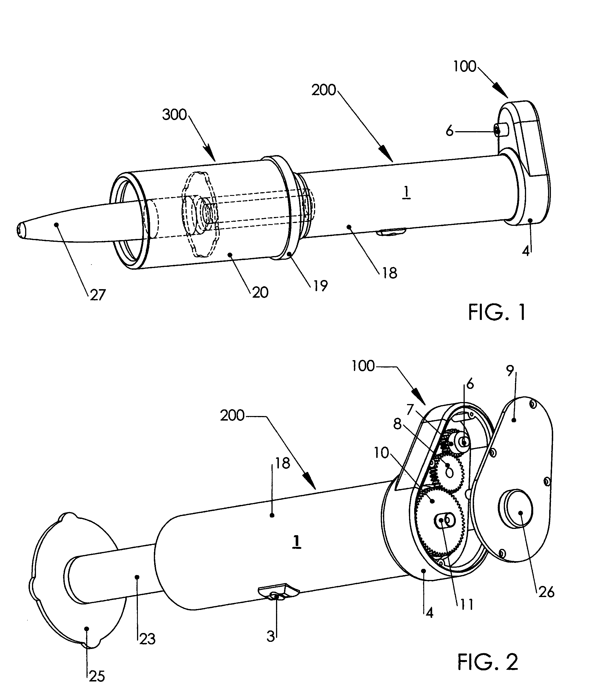
[0045]FIG. 1 shows the assembled device with the attachments assembly configured for use by females. The female stimulation device 27 is shown attached to the device of the invention but is not part of the invention. The attachments assembly for the male configuration is longer and includes a few additional pieces discussed further below.

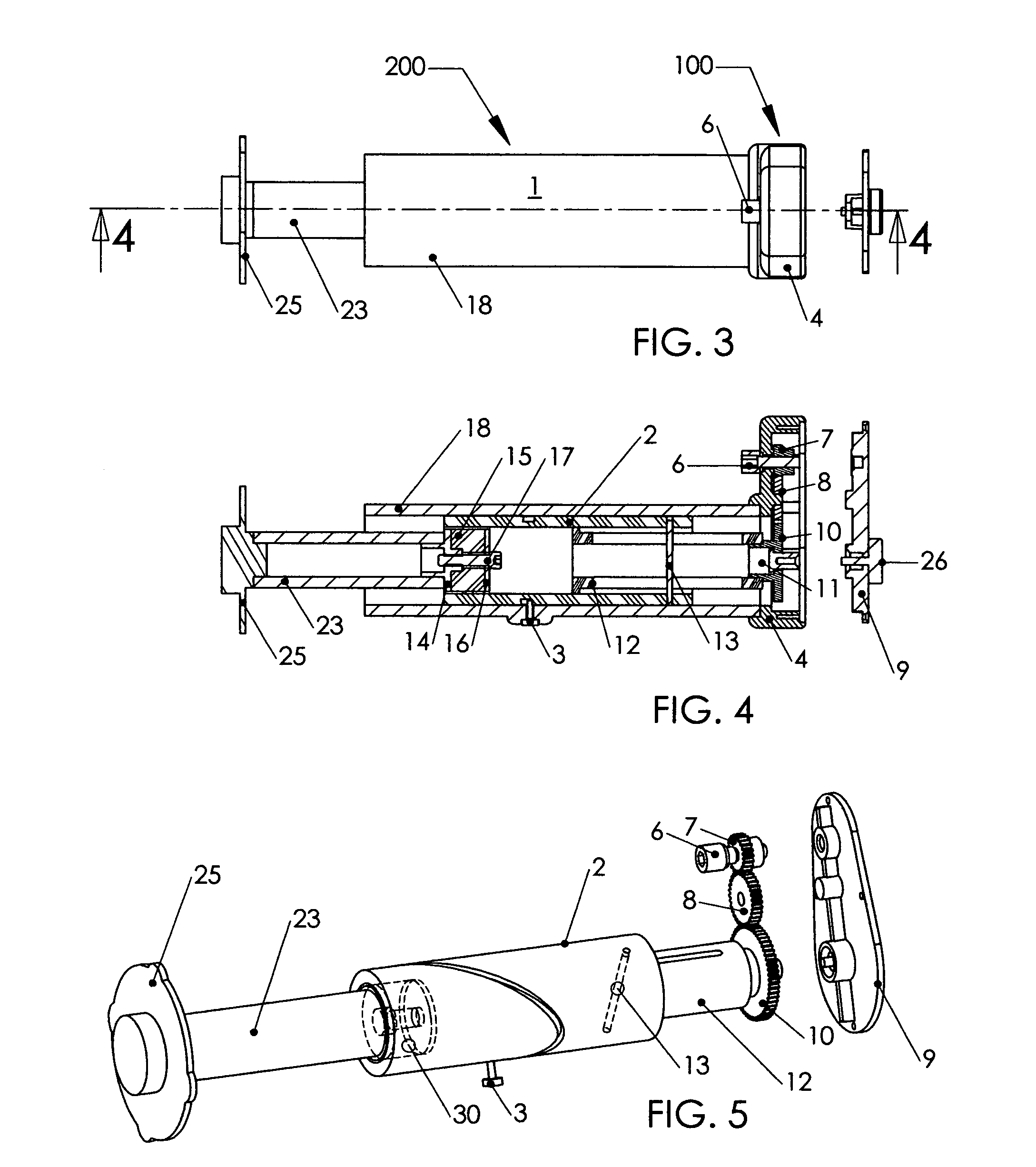
[0046]With reference to FIGS. 1 and 2, the power transmission assembly 1 comprises the key aspect of the invention and contains the majority of its parts. In its preferred form, it is comprised of two major subassemblies; a gearbox assembly 100 and a linear actuation assembly 200. The gearbox housing 4 is rigidly attached to the transmis...


PUM


Abstract

A device designed to take rotary power from an external power source such as a cordless electric screwdriver and transmit that energy into both rotary and reciprocating linear activation of sexual devices used by both males and females for the purpose of masturbation and auto-stimulation is disclosed. The combination of rotational stimulation with reciprocating linear stimulation is apparently remarkably satisfying despite the absence of such stimulation during normal person-on-person sexual contact. The device is simple, light weight, small, powerful, modestly priced, handheld or hands-free, user serviceable, hygienic, gender neutral, sexual orientation neutral, convenient, rugged, multi-motion, safe, reliable, quiet, fully submersible, positionally versatile and sexually satisfying.

Description

BACKGROUND OF THE INVENTION[0001]1. Field of the Invention[0002]The present invention relates to the field of sexual devices used by both males and females for the purpose of sexual auto-stimulation. In particular, the invention relates to mechanical devices adapted to transmit rotary energy into both rotary and reciprocating linear activation for the purpose of masturbation and / or stimulation of one's partner during sexual play.[0003]Various known devices for stimulating the female genitalia have been developed for the purpose of providing sexual gratification and climax during sexual intercourse, foreplay, and masturbation. Generally, they are used for personal pleasure and recreation by providing the user healthy sexual outlets. They are sometimes used in combination with sex-therapy programs. The sexual devices can provide the user an opportunity for sexual exploration and development, alleviate fears and anxiety about sexual performance, aid in the development of one's sensual ...

Claims


Application Information

Patent Timeline
07 Jun 2005
Publication
US6902525B1
IPC
A61D7/00; A61B17/42; A61B17/43; A61H15/00; A61H19/00; A61H7/00; A61F5/00
CPC
A61H19/44; A61H19/32; A61H2201/0153; A61H2201/1664; A61H2201/1671; A61H2201/1418
Inventors
JEWELL, STEPHEN W.