Timed switch control for electric devices

a technology of electric devices and switches, applied in the direction of coupling device connections, instruments, horology, etc., can solve the problems of affecting the safety of users, affecting the use of switches, etc., to facilitate easy and frequent use, facilitate access, and facilitate us

Inactive Publication Date: 2005-06-07
DUNFIELD LINDA WILLIAMS +1
View PDF17 Cites 26 Cited by
  • Summary
  • Abstract
  • Description
  • Claims
  • Application Information

AI Technical Summary

Benefits of technology

[0011]It is an object of the invention to provide a on / off / timer control unit that (1) does not need to have the current time of day set therein; (2) is easily accessed and may be placed on a horizontal surface, such as a tabletop, a desk or a nightstand, or mounted oh a vertical surface, such as a wall or headboard; (3) does not need to be located near an electrical outlet; (4) is not preprogrammed; and (5) may be spontaneously set, to facilitate easy and frequent usage.
[0012]Another object of the invention is to provide an on / off / timer control unit which is quiet and will not disturb sleeping or concentrating or enjoyment of other listening.
[0013]A further object of the invention is to provide an on / off / timer control unit which is easy to use, has simple operating protocols, and has large, easily seeable and reachable control buttons.
[0014]Another object of the invention is to provide an on / off / timer control unit which is easy to set for predetermined, short intervals.

Problems solved by technology

For many people, including seniors, the arthritic, those who are convalescing, or those with physical disabilities, twisting and reaching for small buttons, such as those on a radio, or switches, such as those under a lamp shade, can be painful, and in some cases, dangerous.
Furthermore, the mere act of manipulating and grasping some switches may be extremely difficult for those with arthritic hands or similar mobility disabilities.
Leaving electric devices on when not needed wastes energy, money and may constitute a safety hazard.
At other times, some people, including young children, may wish to be comforted by an electric devices while falling asleep, by having a lamp, television, fan and / or audio unit on, however, when the user falls asleep, the electric device continues to operate, wasting energy, money and possibly creating an unsafe condition.
Many timer devices have been provided to resolve the aforementioned problems, however, most timing devices are complex, are installed in inconvenient locations, and may be difficult to operate, especially by those with physical and / or mental impairments.
A reader may become so involved in reading that they lose track of time.
This event, while pleasurable at the time, may result in an inadequate amount of sleep.
Conventional timers, which can be programmed by a user provide a set operation time, however, because they must be plugged in right at the wall outlet, they may be inaccessible and inconvenient when a user desire to use the timer spontaneously, or when the user desires to change a timer setting.
Thus if the user falls asleep, electric devices remain powered on, thus wasting energy and money.
This device does not require a user to remain awake, however, the timer must be preprogrammed and not easily accessible when a use has a spontaneous need to change the timer.
Furthermore, as the device of the '471 patent must be located near a wall outlet, which is usually located at a low level, and is frequently located behind furniture, accessibility and spontaneity are difficult.
This timer and power switch addresses the accessibility, ease-of-use and timing issues, however, it requires a hard-wired installation, as it must be electrically connected to a wall switch.
There are other known wall switch timers, which require rotation of a setting mechanism, which audibly clicks down the time, which may be an annoyance, especially when one is trying to fall asleep.
Other wall switch timers that silent and require a user only to press a switch or button, however, such timers still require installation of the unit into the wall switch box.

Method used


Image

  • Timed switch control for electric devices
  • Timed switch control for electric devices
  • Timed switch control for electric devices

Examples


first embodiment

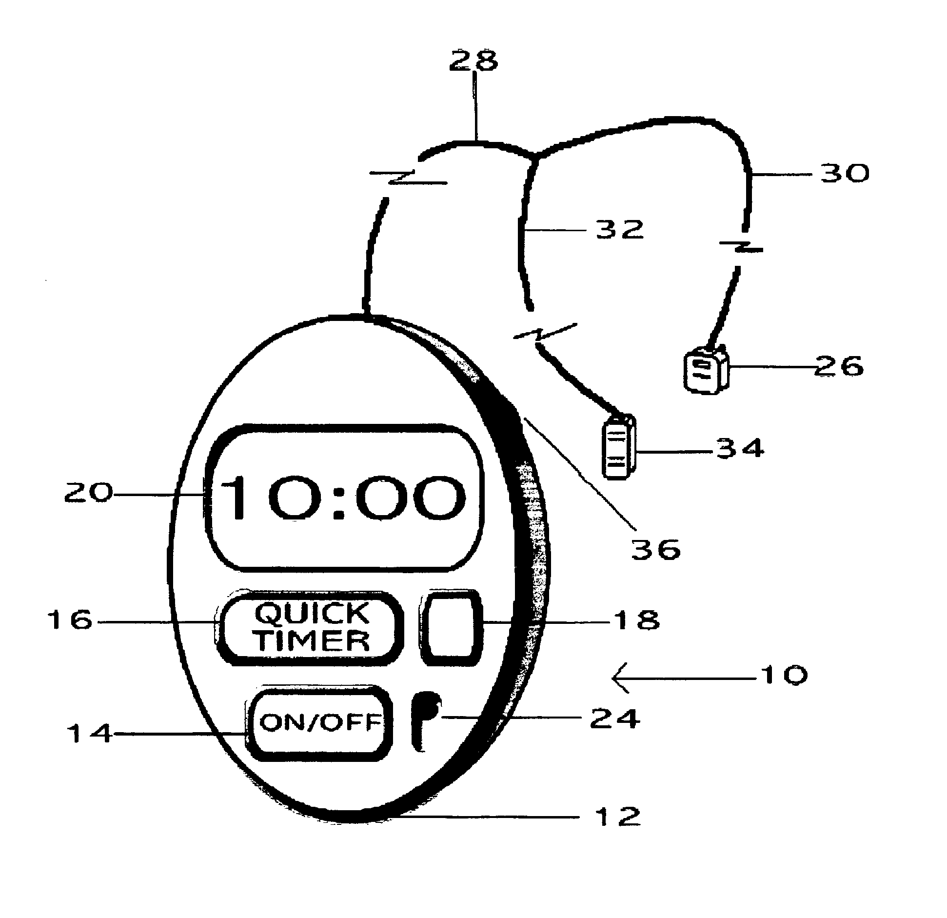
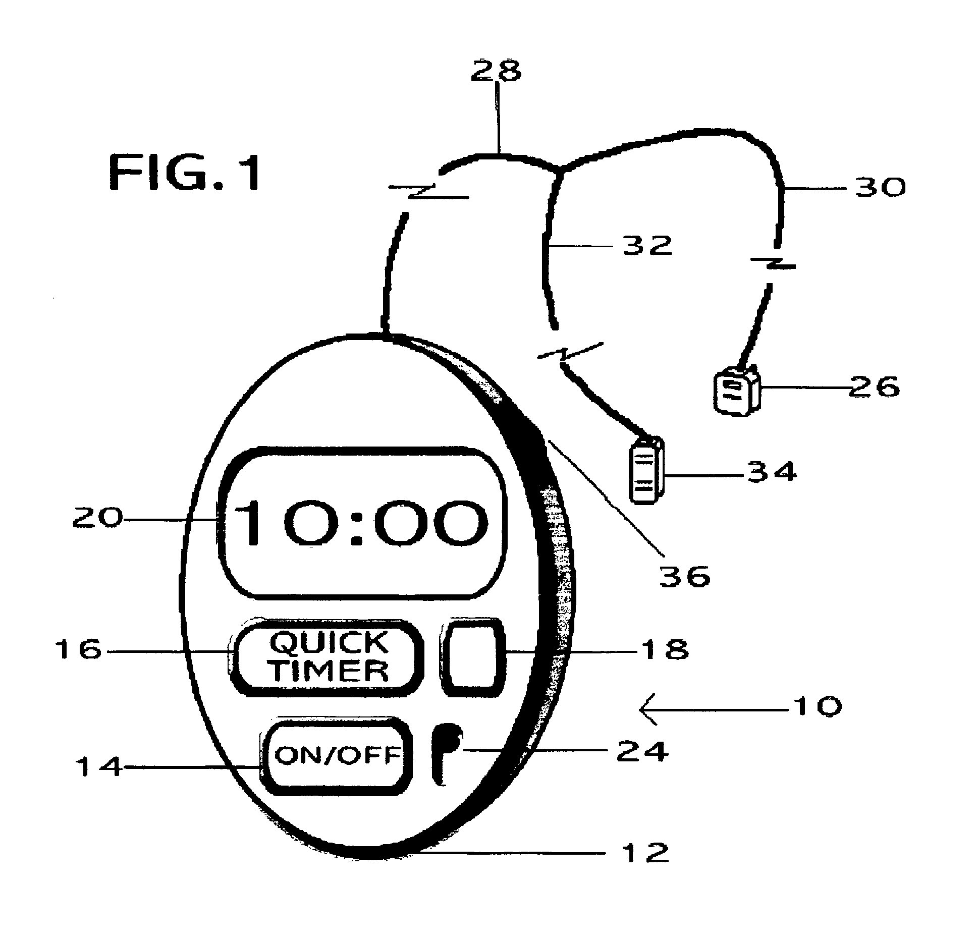
[0021]FIG. 1 is a perspective view of a power switch control unit 10 of the invention, which embodiment is intended for use on a horizontal surface. Unit 10 includes a housing 12, which may have, in the preferred embodiment, dimensions of approximately four and one-half inches in length, three inches in width and about one-half inch in thickness. Housing 12, in the preferred embodiment, has an oval shape. Housing 12 may be formed of plastic, wood, metal or other attractive and serviceable compositions. Housing 12 may include a clip-on, changeable shell, which allows for customization and decorative choices.

[0022]An on / off button 14 may be located on housing 12, and may have the preferred dimensions of one inch by one-half inch, and may or may not have a textured surface for sensory / tactile identification. The large on / off button size facilitates easy use by the mobility / sensory impaired. Pressing on / off button 14 turns a connected-electric device on or off.

[0023]Housing 12 contains ...

second embodiment

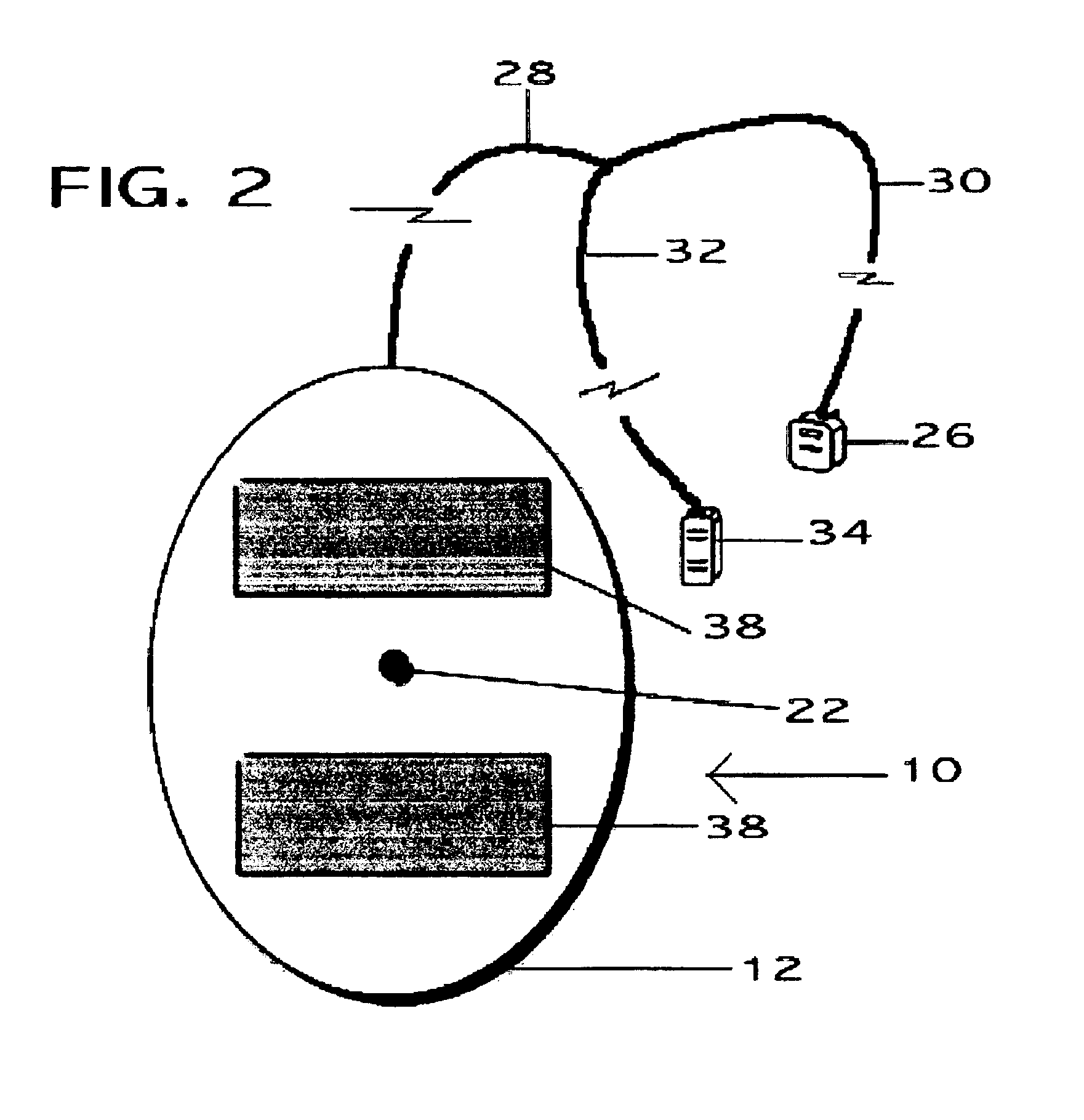
[0029]FIG. 2 depicts a bottom plan view of unit 10, showing non-slip pads 38, which are affixed to housing 12 to reduce slippage and movement. FIG. 3 depicts power switch control unit 40, which includes, as shown in FIG. 4, mounts 42 suitable for mounting unit 40 on a vertical surface, such as a wall, headboard, cabinet, etc. The remaining features of FIGS. 3 and 4 are as in FIGS. 1 and 2, and bear similar reference numbers.

[0030]Unit 10 housing 12 and buttons 14, 16, 18 and switch 24 may be offered with a smooth surface, which make the unit easier to clean. Housing 12 may also be fabricated with embossed button pads having plastic overlays over electronic switches, so that the surface is integral, smooth and easy to keep clean. The embossed button pads eliminate mechanical buttons, which protrude through the panel and allow dirt to collect in the cracks and crevices around the buttons.


PUM


Abstract

A power switch control unit for controlling the operation of a controlled electric device connected to the unit includes a housing having a timing mechanism therein; a power cord having a plug on one end thereof, for connection to a power supply, and having the housing on the other end thereof, for supplying electrical power to the unit and to a connected-electric device controlled by the power switch control unit, and a receptacle for receiving a power cord from an electric device to be controlled by the power switch control unit; control buttons, including: an on / off button for connecting a controlled electric device to the power supply; a timer activation button for activating the timing mechanism, wherein, when the timing mechanism is activated, it connects a controlled electric device to the power supply for a predetermined amount of time in a timed cycle, and then disconnects the connected-electric device from the power supply; and a clear timer button for terminating the predetermined amount of time, and a display for displaying time remaining in the predetermined period of time.

Description

FIELD OF THE INVENTION[0001]This invention relates to switch controls for electric devices, and specifically to a switch control which facilitates operation of electric devices by mobility impaired individuals.BACKGROUND OF INVENTION[0002]For many people, including seniors, the arthritic, those who are convalescing, or those with physical disabilities, twisting and reaching for small buttons, such as those on a radio, or switches, such as those under a lamp shade, can be painful, and in some cases, dangerous. Lamps may tip over or hands may contact hot light bulbs. Furthermore, the mere act of manipulating and grasping some switches may be extremely difficult for those with arthritic hands or similar mobility disabilities. Many devices have been provided to resolve the problems of accessibility and ease-of-use of power switches.[0003]People with impaired memory, such as attention deficit hyperactivity disorder (ADHD), autism, Alzheimer's Disease, senile dementia, or the like, or tho...

Claims


Application Information

Patent Timeline
Patent Type & Authority Patents(United States)
IPC IPC(8): G04G15/00
CPCG04G15/003
Inventor DUNFIELD, LINDA WILLIAMSDUNFIELD, JOHN STEPHEN
Owner DUNFIELD LINDA WILLIAMS
Why Eureka
Try Eureka