Induction machine with motor and generator operation modes

Inactive Publication Date: 2005-06-07
DENSO CORP
View PDF11 Cites 9 Cited by
  • Summary
  • Abstract
  • Description
  • Claims
  • Application Information

AI Technical Summary

Benefits of technology

[0010]According to another feature of the invention an electric machine operating as one of a generator mode and a motor mode includes a stator core having a plurality of teeth and slots, a multi-phase armature winding, a field coil mounted in the stator core to form main magnetic field, a moving core having a plurality of salient poles so as to move relative to the stator core to cross the main magnetic field, a first controller for supplying field current to the field coil according t

Problems solved by technology

Because such a dc motor has brushes, the lifetime is limited.
Although an ac rotary electric machine with a two-way power converter or an inverter has been used as the generator-motor recently,

Method used


Image

  • Induction machine with motor and generator operation modes
  • Induction machine with motor and generator operation modes
  • Induction machine with motor and generator operation modes

Examples


Embodiment Construction

[0018]A preferred embodiment of the invention is described with reference to the appended drawings.

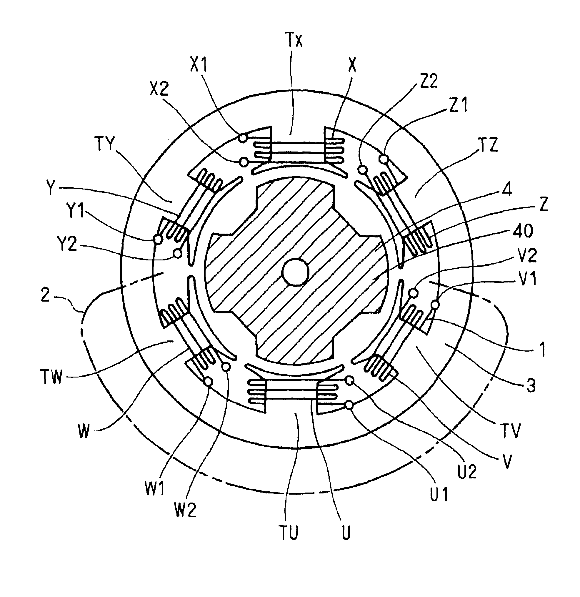
[0019]A rotary electric machine comprises a three-phase start connected armature winding 1 having six phase coils X, Y, Z, U, V, and W, a field coil 2, a stator core 3 having six teeth TX, TY, TZ, TU, and TW and a magnetic inductor rotor 4 having four salient poles 40. The phase coil X has terminals X1 and X2, the phase coil Y has terminals Y1, and Y2, the phase coil X has terminals Z1 and Z2, the phase coil U has terminals U1 and U2, the phase coil V has terminals V1 and V2, and the phase coil W has terminals W1 and W2. Each phase coil has 7 turns and is connected in series to another that is 180° in electric angle different therefrom to form one three phase-windings of a three-phase star-connected armature winding having three output terminals, as shown in FIG. 2. The output terminals are connected to a full-wave three-phase rectifier unit 6. The field coil 2 has 200 turns and accomm...


PUM


Abstract

An electric machine selectively operates as a generator mode or a motor mode. The electric machine includes a stator core, a multi-phase armature winding, a field coil, a moving core having a plurality of salient poles so as to move relative to the stator core to cross the magnetic field. Field current is supplied to the field coil differently according to operation mode. A portion of the armature winding is short-circuited to form an additional magnetic field that has a phase different from the magnetic field of the field coil. Therefore, the rotary core moves relative to the stator core when the operation mode is in the motor mode.

Description

CROSS REFERENCE TO RELATED APPLICATION[0001]The present application is based on and claims priority from Japanese Patent Application 2001-392246, filed Dec. 25, 2001, the contents of which are incorporated herein by reference.BACKGROUND OF THE INVENTION[0002]1. Field of the Invention[0003]The present invention relates to a rotary electric machine and, particularly, a generator-motor.[0004]2. Description of the Related Art[0005]A dc electric rotary machine has been used as a generator-motor for a long time. Because such a dc motor has brushes, the lifetime is limited. Although an ac rotary electric machine with a two-way power converter or an inverter has been used as the generator-motor recently, the inverter necessitates many power transistors of a large capacity to control a large amount of multi-phase current, resulting in an expensive motor-generator having a complicated structure.SUMMARY OF THE INVENTION[0006]Therefore, the present invention has been made in view of the above p...

Claims


Application Information

Patent Timeline
IPC IPC(8): H02K19/10H02K19/02H02K19/24H02K19/16H02P9/00H02P9/40H02K1/24
CPCH02K19/103H02P9/40H02K19/24
Inventor KUSASE, SHINSHIGA, TSUTOMU
Owner DENSO CORP
Why Eureka
Try Eureka