Complex electromagnetic relay

a technology of electromagnetic relays and complex electromagnetic relays, applied in the direction of electromagnetic relay details, non-polarised relays, relays, etc., can solve the problems of difficult to reduce the dimension of the housing, the number of parts and the number of assembly steps is increased, and the dimension of the complex electromagnetic relay is increased especially. , to achieve the effect of reducing the dimension in the height direction

Inactive Publication Date: 2005-06-07
FUJITSU COMPONENENT LTD
View PDF9 Cites 20 Cited by
  • Summary
  • Abstract
  • Description
  • Claims
  • Application Information

AI Technical Summary

Benefits of technology

[0007]It is an object of the present invention to provide a complex electromagnetic relay including a plurality of relay structures accommodated in a common housing, which are configured respectively as electromagnetic relays independent of each other, in a mutually inverted orientation with the contact sections thereof being located alternately at opposing sides, wherein it is possible to reduce the dimension in a height direction as well as the numbers of parts and assembling steps, and wherein it is possible to ensure a desired insulation distance between the relay structures disposed side-by-side.

Problems solved by technology

In this arrangement, problems may arise due to the presence of the base block, in that the dimension of the complex electromagnetic relay is increased especially in a height direction, and that the numbers of parts and of assembling steps are increased.
Further, in this arrangement, it may be difficult to reduce the dimension of a housing while ensuring a desired insulation distance or clearance between the relay structures disposed side-by-side or, in particular, between armatures as actuating elements, in the respective electromagnet assemblies.

Method used


Image

  • Complex electromagnetic relay
  • Complex electromagnetic relay
  • Complex electromagnetic relay

Examples


Embodiment Construction

[0021]The embodiments of the present invention are described below in detail, with reference to the accompanying drawings. In the drawings, the same or similar components are denoted by common reference numerals.

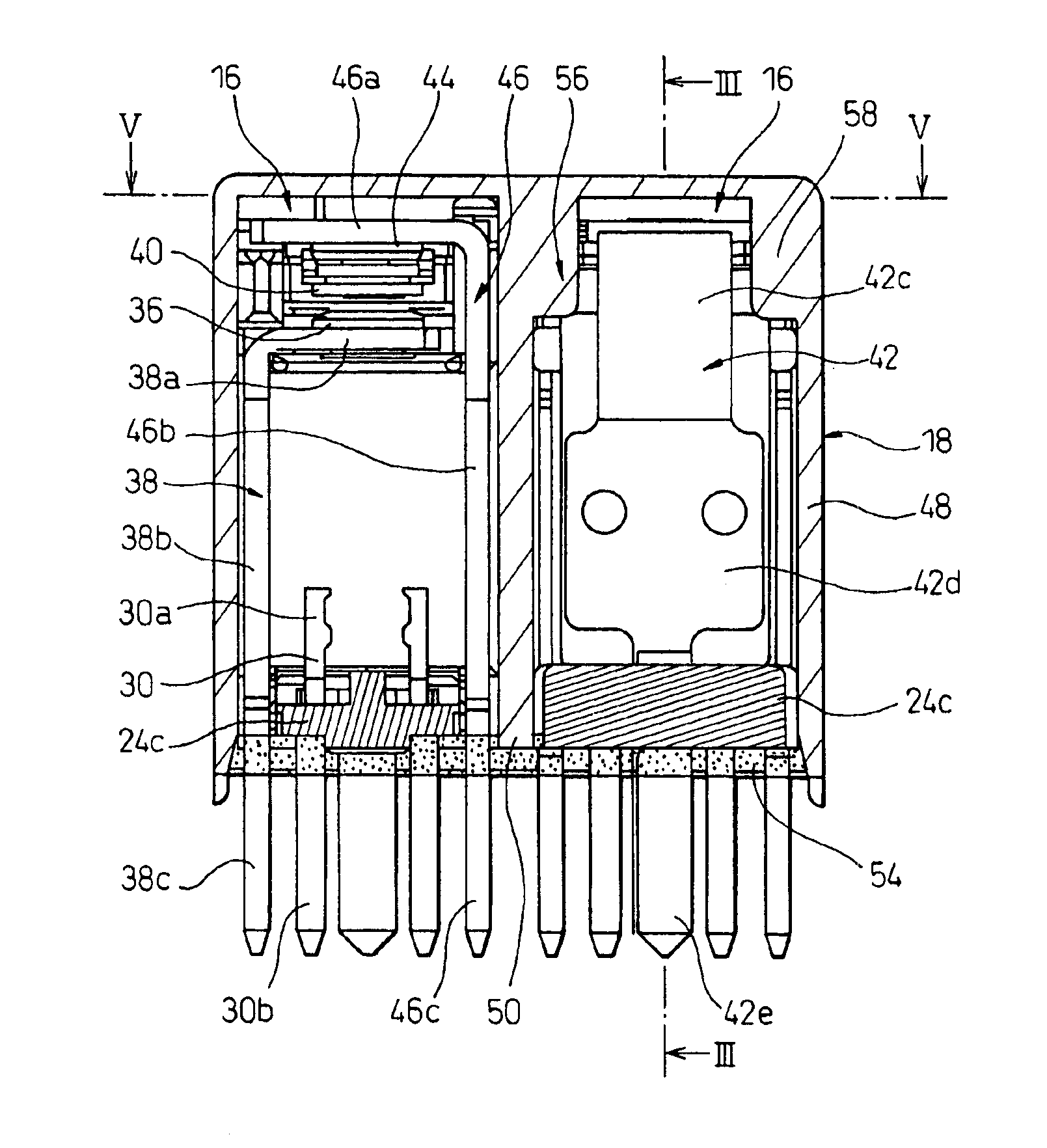
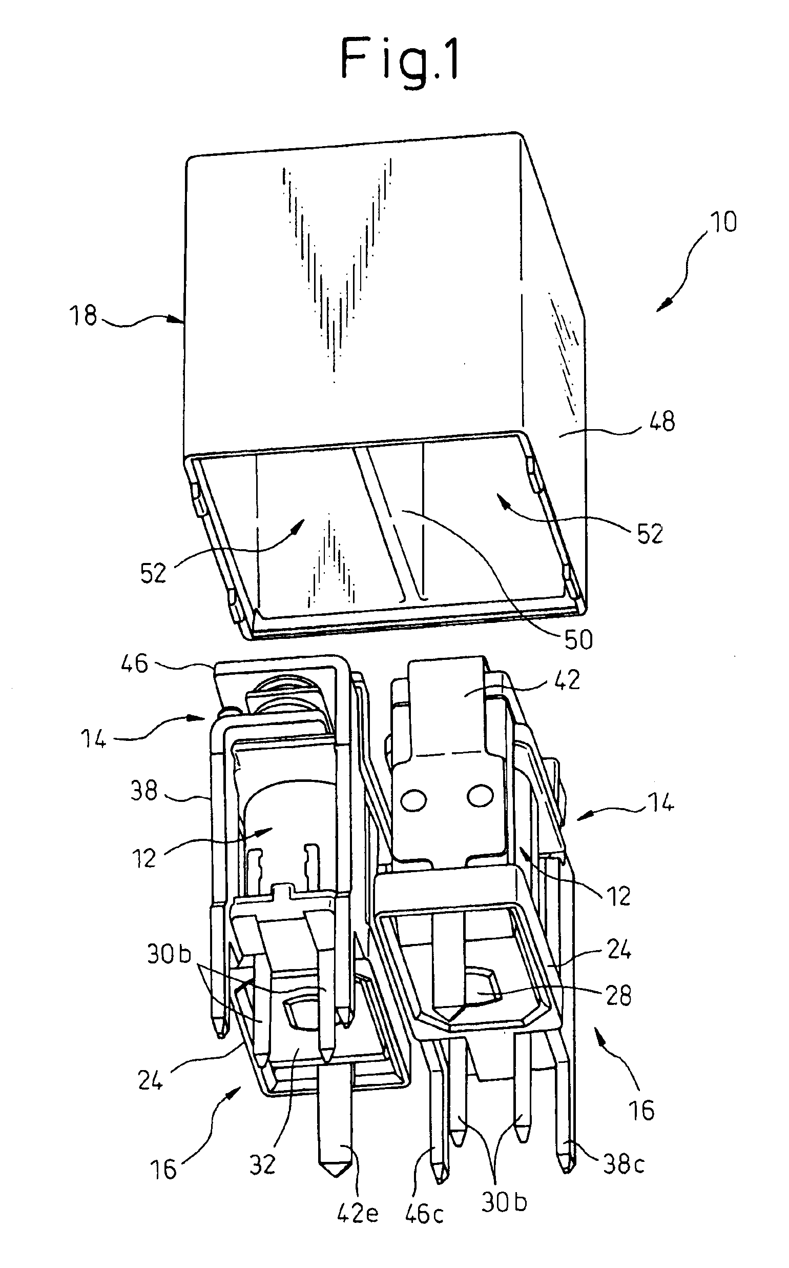
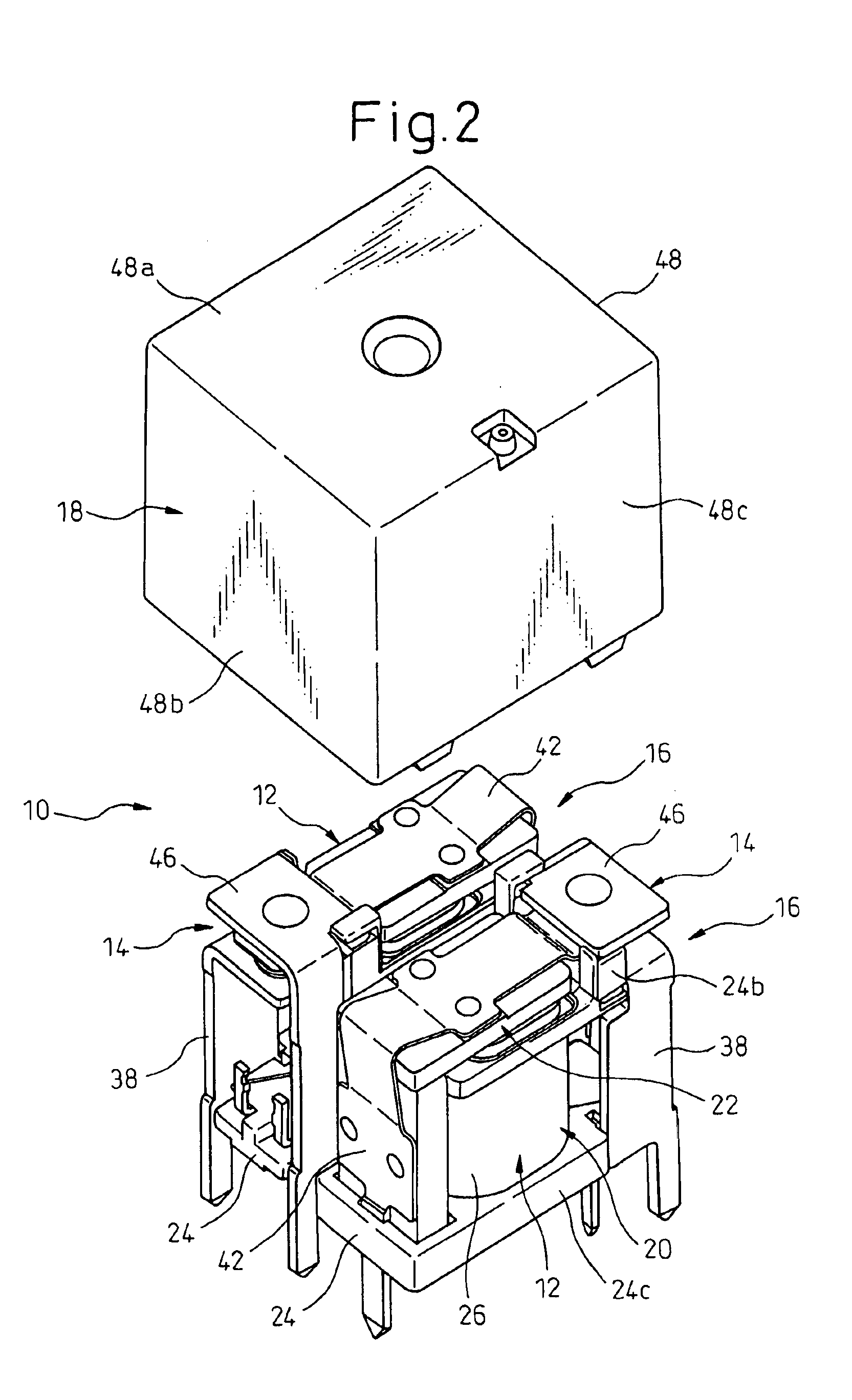
[0022]Referring to the drawings, FIG. 1 is an exploded perspective view showing a complex electromagnetic relay 10, according to one embodiment of the present invention, as viewed from the bottom side thereof; FIG. 2 is an exploded perspective view showing the complex electromagnetic relay 10 as viewed from the top side thereof; and FIGS. 3 to 5 are sectional views of the complex electromagnetic relay 10. AS shown in FIGS. 1 and 2, the complex electromagnetic relay 10 includes a pair of relay structures 16 configured respectively as electromagnetic relays independent of each other, each relay structure including an electromagnet assembly 12 and a contact section 14 acting to open or close in accordance with the operation of the electromagnet assembly 12; and a housing 18 acc...


PUM


Abstract

A complex electromagnetic relay including a plurality of relay structures configured respectively as relays independent of each other, each relay structure including an electromagnet assembly and a contact section acting to open or close in accordance with an operation of the electromagnet assembly; and a housing accommodating the relay structures in a mutually inverted orientation with contact sections of the relay structures being located alternately at opposing sides. The electromagnet assemblies in the relay structures are provided individually with bobbins supporting coils. The housing includes an enclosing wall enclosing the relay structures in an envelope-like manner and a partition wall arranged between the relay structures disposed side-by-side to separate the relay structures from each other. The bobbins of the electromagnet assemblies are fixedly attached to the enclosing wall as well as to the partition wall.

Description

BACKGROUND OF THE INVENTION[0001]1. Field of the Invention[0002]The present invention relates generally to an electromagnetic relay and, more particularly, to a complex electromagnetic relay including a plurality of relay structures, accommodated in a common housing, which are configured respectively as electromagnetic relays functionally independent of each other.[0003]2. Description of the Related Art[0004]There is known a complex electromagnetic relay including a plurality of relay structures accommodated in a single common housing in a side-by-side arrangement, wherein the respective relay structures are configured as electromagnetic relays functionally independent of each other and wherein each relay structure includes an electromagnet assembly and a contact section acting to open or close in accordance with the operation of the electromagnet assembly. This type of complex electromagnetic relay can be used in a control circuit frequently switching the operation of a motor or a ...

Claims


Application Information

Patent Timeline
Patent Type & Authority Patents(United States)
IPC IPC(8): H01H50/04H01H50/02H01H45/00H01H45/02H01H51/20
CPCH01H50/042H01H50/023H01H50/026H01H2050/049H01H2050/044
Inventor NAKAMURA, AKIHIKOAOKI, SHIGEMITSUSASO, HIROFUMI
Owner FUJITSU COMPONENENT LTD
Why Eureka
Try Eureka