Optical pickup

a pickup and optical technology, applied in the field of optical pickups, can solve the problem of inadvertent attachment of the distortion gel to the objective lens

Inactive Publication Date: 2005-06-07
ALPINE ELECTRONICS INC
View PDF6 Cites 8 Cited by
  • Summary
  • Abstract
  • Description
  • Claims
  • Application Information

AI Technical Summary

Benefits of technology

[0011]In order to solve the problem described above, it is an object of the present invention to provide an optical pickup that can prevent the projections of a cleaner for cleaning dirt attached to the objective lens from being brought into contact with the damper gel.
[0014]Since the damper gel does fill the gap at the position around linear spring members other than the linear spring member at the position closest to the optical disk, the function of damping deflection of the linear spring members is not hindered.
[0017]In the construction described above, by setting the gap between the supporting member and the edge defining the opening of the branch hole at the closest position with respect to the optical disk out of the plurality of branch holes opened toward the supporting member to a value larger than the gap between the supporting member and the edge defining the openings of other branch holes opened toward the supporting member, even when the damper gel temporarily protrudes from the opening of the branch hole at the closest position with respect to the optical disk when the damper gel is injected into the hole on the holding member in a predetermined quantity under a predetermined pressure, the damper gel may be prevented from being brought into contact with the supporting member, and only the damper gel projecting from the openings of the branch holes other than the branch hole at the closest position with respect to the optical disk may fill the gap. Therefore, the damper gel can be injected into the predetermined position in the gap by only one filling operation.
[0018]In the construction described above, by setting the area of the opening of the branch hole at the closest position with respect to the optical disk out of the plurality of branch holes opened toward the supporting member to a value smaller than the area of the opening of other branch holes opened toward the supporting member, the quantity of the damper gel flowing out from the opening of the branch hole at the closest position with respect to the optical disk into the gap may be reduced relative to the quantity of the damper gel flowing out from the openings of other branch holes into the gap when the damper gel is injected into the holes on the holding member. Therefore, the damper gel may be prevented from filling the gap on the optical disk side.
[0019]In the construction described above, by providing a filler hole for injecting the damper gel into the holes on the holding member at a position not facing toward the optical disk, the projections of the cleaner may be prevented from being brought into contact with damper gel exposed from the filler hole.
[0020]In the construction described above, by communicating the filler hole with a branch hole other than the branch hole at the closest position with respect to the optical disk out of the plurality of branch holes, when the damper gel is filled therein, abrupt flow-in of the damper gel into the branch hole at the closest position with respect to the optical disk may be prevented. Therefore, in this case as well, the damper gal may be prevented from flowing out of the opening of the branch hole opened toward the supporting member, and the damper gel is reliably prevented from filling the gap near the optical disk.

Problems solved by technology

Therefore, in the conventional optical pickup described above, when a cleaner having projections such as a brush or the like is used on the optical disk for wiping off dirt attached to the optical lens, the projections of the cleaner come into contact with the damper gel filling the gap between the holding member for holding the damper gel and the supporting member for supporting the linear spring, which may result in the damper gel being inadvertently attached to the objective lens.

Method used


Image

  • Optical pickup
  • Optical pickup
  • Optical pickup

Examples


Embodiment Construction

[0030]Referring now to the drawings, an embodiment of the optical pickup according to the invention will be described.

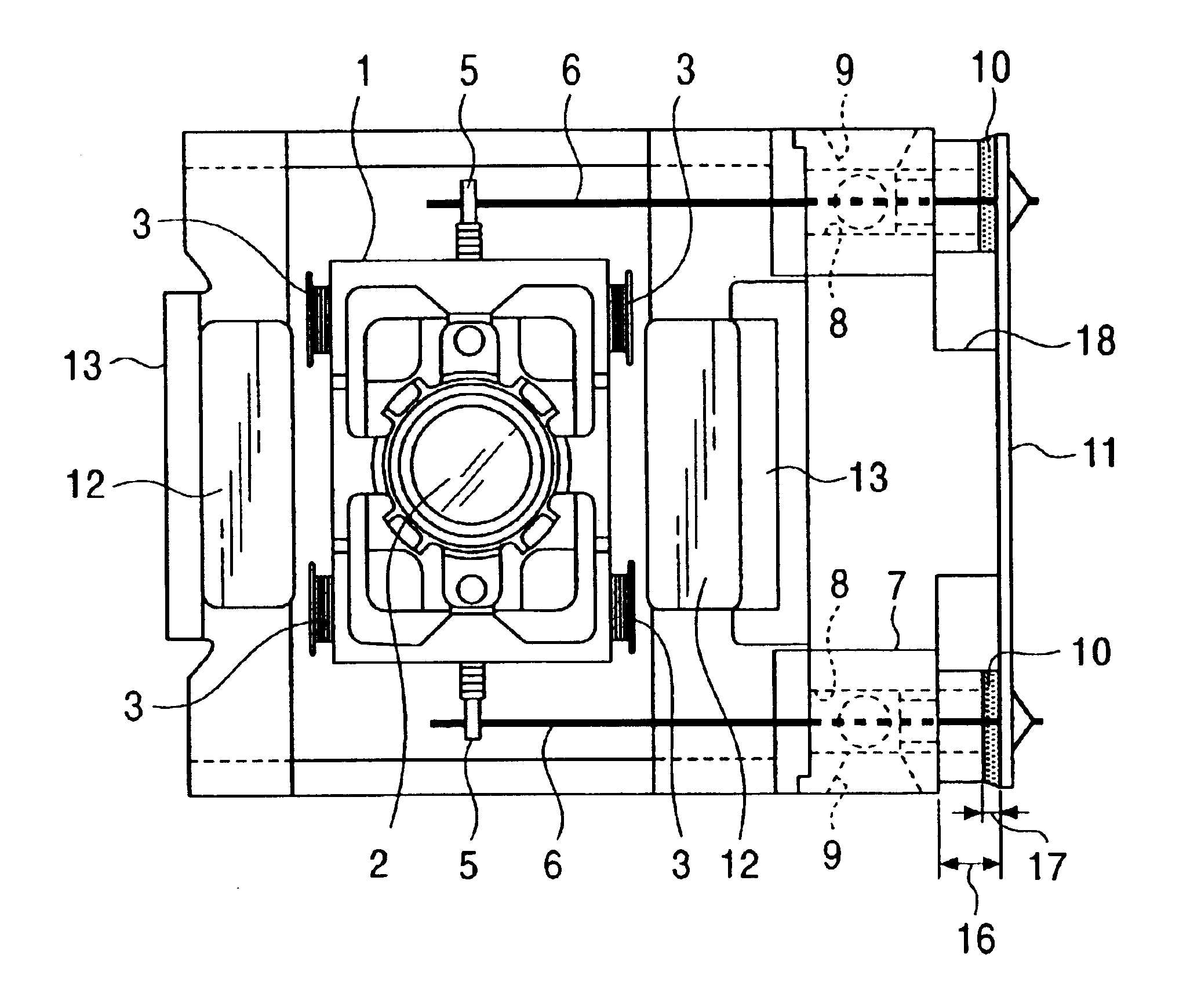
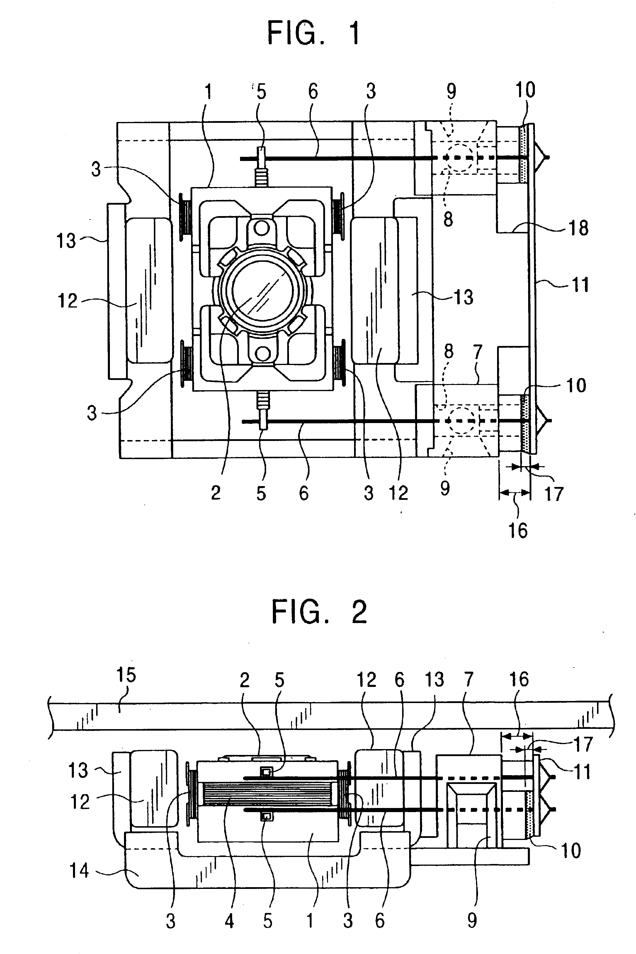
[0031]The optical pickup of the present embodiment records information on an optical disk such as a DVD and / or reproduces information recorded on the optical disk, and, as shown in FIGS. 1 and 2, includes an objective lens 2 for converging a light beam onto an optical disk 15, a lens holder 1 for holding the objective lens 2, a magnetic drive mechanism for driving the lens holder 1 in the focusing direction (vertical direction in FIG. 2) and the tracking direction (vertical direction in FIG. 1), a supporting mechanism for supporting the lens holder 1 so as to be capable of moving in the focusing direction and in the tracking direction and functioning as a suspension for the lens holder 1, and a chassis for mounting a light-emitting and light-receiving elements or various optical components.

[0032]The magnetic drive mechanism includes a focus coil 4 wound around the si...


PUM

PropertyMeasurementUnit
areaaaaaaaaaaa
magnetic fluxaaaaaaaaaa
lengthaaaaaaaaaa

Abstract

In an optical pickup including a supporting member for movably supporting a lens holder through a plurality of linear spring members, a holding member is provided between the lens holder and the supporting member and having holes for accommodating a plurality of linear spring members, and a damper gel is filled in the holes in the holding member for damping deflection of the linear spring member. Gaps are formed between the edge defining an opening of the hole on the holding member opened toward the supporting member and the supporting member, and the damper gel is not filled around the linear spring member at the closest position with respect to the optical disk but is filled around other linear spring members. Accordingly, when wiping off dirt attached to the objective lens, the damper gel is prevented from attaching on projections of the cleaner even when the projections pass through the gap formed between the holding member and the supporting member.

Description

BACKGROUND OF THE INVENTION[0001]1. Field of the Invention[0002]The present invention relates to an optical pickup for recording information on an optical disk such as a DVD (digital versatile disk) and / or reproducing information recorded on the optical disk, and, more specifically, to an optical pickup in which a linear spring member for movably supporting a lens holder is surrounded by damper gel so as to be capable of actively damping deflection of the linear spring member.[0003]2. Description of the Related Art[0004]Conventionally, the optical pickup for recording on and / or reproducing information from the optical disk such as a DVD includes an objective lens for converging a light beam on the optical disk, a lens holder for holding an objective lens, a magnetic drive mechanism for driving the lens holder in the focusing direction and in the tracking direction, a supporting mechanism movably supporting the lens holder and functioning as a suspension for the lens holder, and a ch...

Claims


Application Information

Patent Timeline
Patent Type & Authority Patents(United States)
IPC IPC(8): G11B7/09G11B7/12G11B7/121
CPCG11B7/121G11B7/0932
Inventor WADA, MITSUNORI
Owner ALPINE ELECTRONICS INC
Why Eureka
Try Eureka