Method and device for defining elastic deformations and internal angle of a gyratory compactor

a gyratory compactor and elastic deformation technology, applied in the direction of mechanical measuring arrangements, instruments, mechanical means, etc., can solve the problems of troublesome and slow kind of study of test results, inaccurate measurement results gathered with this kind of method, and especially serious situations, so as to achieve easy and reliable expression of the quality of a gyratory compactor based on elastic properties, accurate and reliable, and quick and easy to use

Inactive Publication Date: 2005-06-14
PINE INSTR
View PDF30 Cites 4 Cited by
  • Summary
  • Abstract
  • Description
  • Claims
  • Application Information

AI Technical Summary

Benefits of technology

[0008]The purpose of this invention is to provide a method and a device, which reduces or eliminates earlier mentioned problems connected with present methods of defining elastic deformations and internal angles of gyratory compactors. Especially, the purpose of the invention is to provide a method and a device, by use of which the elastic properties of a gyratory compactor frame can be defined. Further by using the method and device, important factors expressing the quality of a gyratory compactor depending on elastic properties are easily and reliably defined. Furthermore, the purpose of the invention is to provide a method, which is quick and easy to use as well as a device, which is accurate and reliable but simple and advantageous by construction.
[0009]Characteristic to the method in accordance with the invention is the fact that a mass specimen is replaced with a load generating device (loading device), where the load level on the gyratory compactor is known, and that the gyratory compactor is used while the load generating device is inside the mold in the gyratory compactor. Using this load generating device where the load level on the gyratory compactor is known, instead of a mass specimen when defining elastic properties and integral angle, errors due to changes in stiffness and density of a mass specimen are eliminated. Furthermore, the beforehand known loading caused by the load generating device may easily be changed to another known value in order to find out reliably and exactly the correlation between elastic deformations of a gyratory compactor and the magnitude of load.

Problems solved by technology

A change in the angle of gyration is usually the most significant factor of error having influence on results in measuring compaction properties in gyratory compactor.
The situation is especially serious when the mass specimen is causing heavier loadings or variable loadings to the gyratory compactor (i.e. a “stiff” or coarse mixture).
This kind of studying of tests and their results is rather troublesome and slow.
Furthermore, measuring results gathered with this kind of method are inaccurate, among other things, because properties and density of mass specimen vary uncontrollably and relatively much, although the mass specimen has been taken from the same mass specimen source.
There are many disadvantages and imperfections connected to the measuring device of U.S. Pat. No. 6,477,783.
Firstly, the measuring device takes part of the space meant for a mass specimen, so that a mass specimen smaller than normal must be used or the compaction pistons are further away from each other than during normal compaction.
When the measuring device is shorter in order to decrease the above mentioned disadvantages, the probe tips must be adjusted closer to each other on the vertical axis, which creates more inaccuracy in measuring.
Furthermore, due to its construction the measuring device is exposed to heat damage while using hot asphalt specimens.
Also impurities may stick to probe tips affecting the measuring accuracy.
These all are additional to elements of uncertainty in use of the measuring device as well as difficulties in measuring process presented in patent above.

Method used


Image

  • Method and device for defining elastic deformations and internal angle of a gyratory compactor
  • Method and device for defining elastic deformations and internal angle of a gyratory compactor
  • Method and device for defining elastic deformations and internal angle of a gyratory compactor

Examples


Embodiment Construction

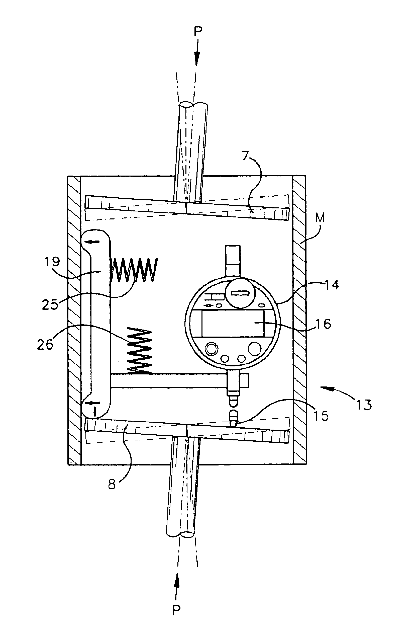
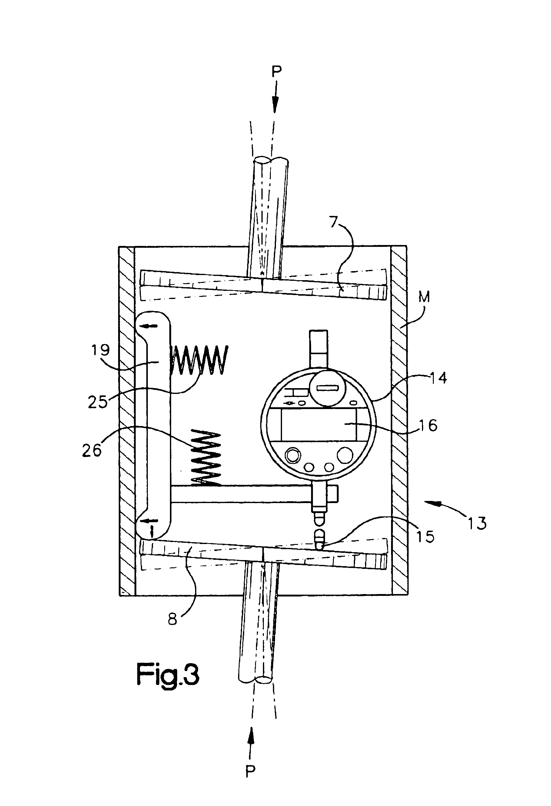
[0025]A device of the invention includes a loading device suitable to be placed into a specimen cylinder mold of a gyratory compactor as well as measuring elements for measuring the angle of gyration and a processing unit for measuring results to be connected to measuring elements for processing the measuring results of the angle of gyration and converting to elastic deformations of a gyratory compactor.

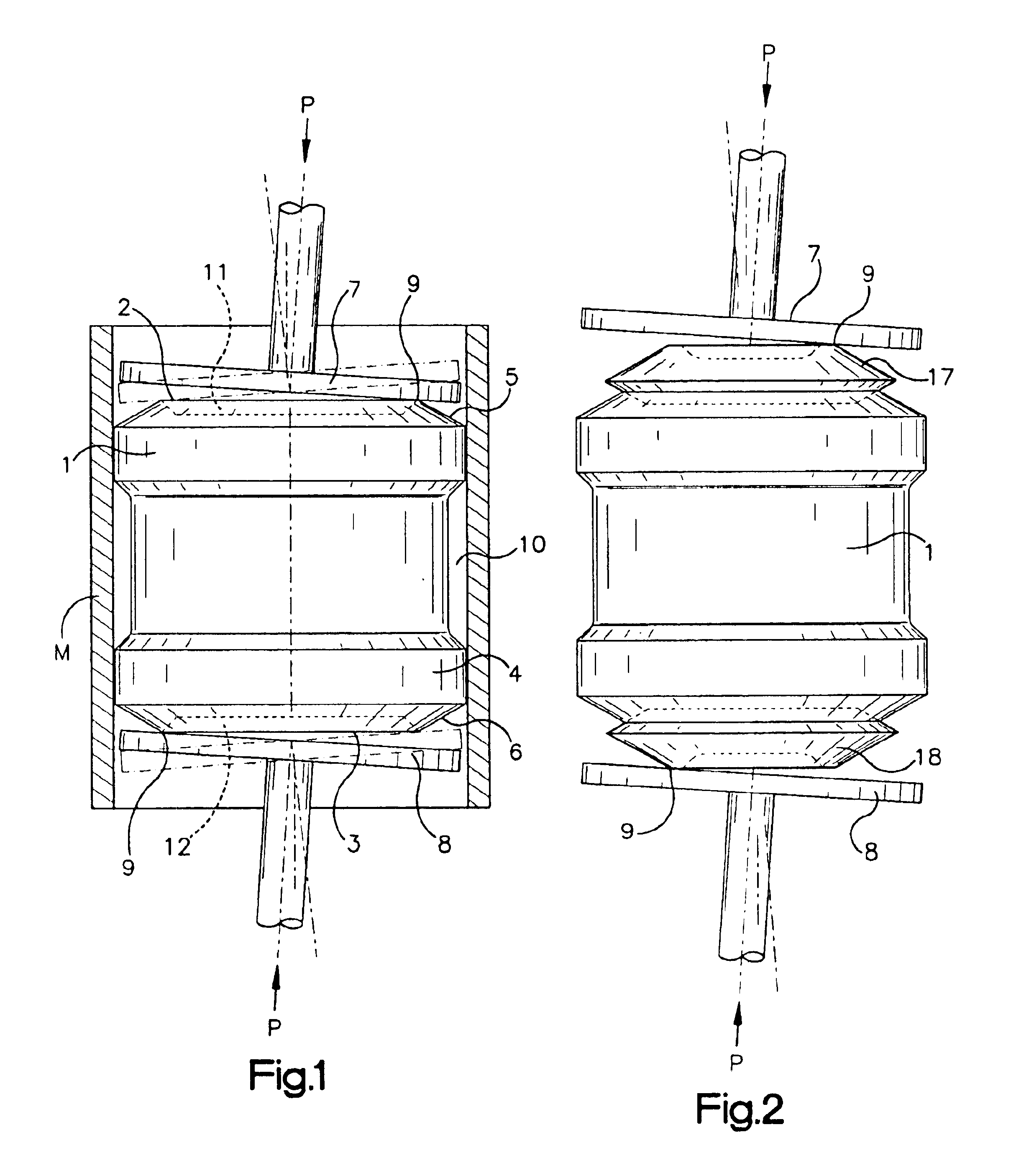
[0026]In FIG. 1 there is a loading device 1 placed into a specimen cylinder mold M of a gyratory compactor. The loading device in accordance with FIG. 1 has been made of suitable solid material, such as steel, aluminum or plastic, with a body in the shape of a cylinder with head surfaces 2 and 3, as well as casing surface 4 between the head surfaces. The head surfaces 2 and 3 extend or project from respective ends of the loading device body. The diameter of the loading device is such that it can be placed inside a standard size specimen cylinder mold of a gyratory compactor with clos...


PUM

PropertyMeasurementUnit
distanceaaaaaaaaaa
angle of gyrationaaaaaaaaaa
diameteraaaaaaaaaa

Abstract

The object of the invention is a method for defining elastic deformations and integral angle between of the most important parts of a gyratory compactor, in which method the angle of gyration of a gyratory compactor is measured during the use of the gyratory compactor. The object of the invention is also a device in accordance with the claim 1, which device includes measuring elements (13, 20, 27, 28) for measuring the angle of gyration of a gyratory compactor. Characteristic to the method in accordance with the invention is the fact that a loading device (1) is adjusted in the place of mass specimen, the loading of which on the gyratory compactor is earlier known and that the gyratory compactor will be in use while the loading device (1) is inside the gyratory compactor. Characteristic to the device in accordance with the invention is the fact that the device includes at least one loading device which can be placed inside the specimen cylinder mold of the gyratory compactor.

Description

CROSS REFERENCE TO RELATED APPLICATIONS[0001]This application claims the benefit of Patent Application No. FI-20020560, filed in Finland on Mar. 22, 2002. This application claims the benefit of Patent Application No. FI-20022035, filed in Finland on Nov. 15, 2002.FIELD OF THE INVENTION[0002]The present invention relates to a method for accurately inducing elastic deformations of a gyratory compactor, and measuring the internal angle of gyration. The internal angle of gyration is the angle formed between the axis of a cylindrical mold and the end plates of the mold.BACKGROUND OF THE INVENTION[0003]A gyratory compactor is used for defining properties of compaction of various masses of soil and similar substances, such as bituminous asphalt. For measurements the specimen mold of a gyratory compactor is filled with mass specimen. The specimen is compressed under vertical pressure and the so called gyratory movement, which causes shear strain across the specimen. These actions make the p...

Claims


Application Information

Patent Timeline
Patent Type & Authority Patents(United States)
IPC IPC(8): G01B5/30G01N3/08G01N3/56G01N3/00G01N3/06G01M99/00G01N1/28
CPCG01N1/286G01N3/08G01N3/565G01N2203/0682G01N2203/0028
Inventor PAAKKINEN, ANTTI
Owner PINE INSTR
Why Eureka
Try Eureka