Laminar-flow airfoil

a technology of airfoil and laminar flow, applied in the field of laminar flow airfoil, can solve the problems of unfavorable low-profile drag, unacceptably low maximum lift coefficient, and higher weight and cos

Inactive Publication Date: 2005-06-14
AIRFOILS
View PDF27 Cites 30 Cited by
  • Summary
  • Abstract
  • Description
  • Claims
  • Application Information

AI Technical Summary

Problems solved by technology

Low profile drag is not possible because the slat introduces disturbances that cause the laminar flow to transition to turbulent flow near the leading edge of the wing.
High-lift systems are complex, both mechanically and structurally, resulting in higher weight and cost.
The pressure-recovery gradient becomes steeper as the extent of the favorable gradient along the forward portion of the airfoil becomes greater, eventually reaching a limit beyond which trailing-edge separation occurs, resulting in an unacceptably low maximum lift coefficient.
The extent of laminar flow is also limited by wing leading-edge sweep, which also constrains the achievement of laminar flow because it introduces cross-flow instabilities into the laminar boundary layer that cause premature transition to turbulent flow.
Surface cooling can also increase the extent of laminar flow although it is not currently considered practical.
LFC systems are very complex, mechanically, structurally, and operationally, resulting in high weight and cost.

Method used


Image

  • Laminar-flow airfoil
  • Laminar-flow airfoil
  • Laminar-flow airfoil

Examples


Embodiment Construction

[0014]Reference will now be made to an embodiment of the invention, an example of which is illustrated in the accompanying drawings

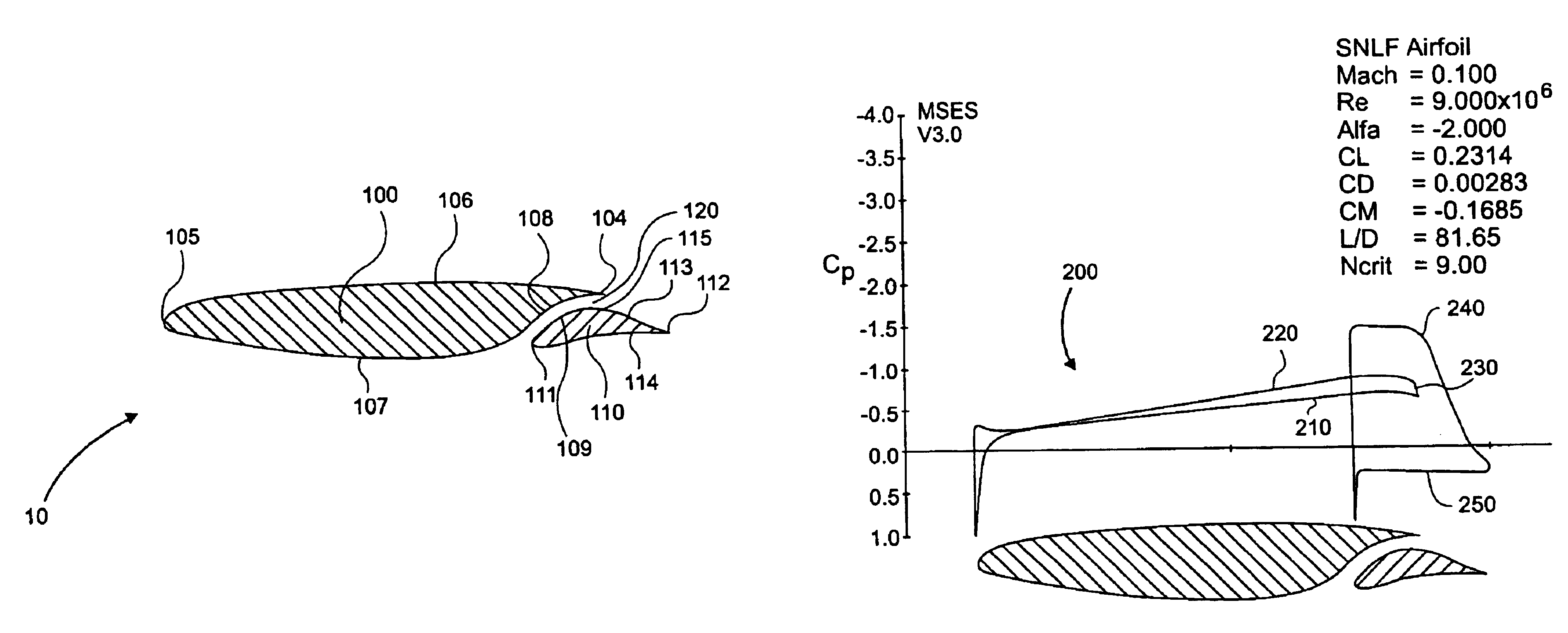
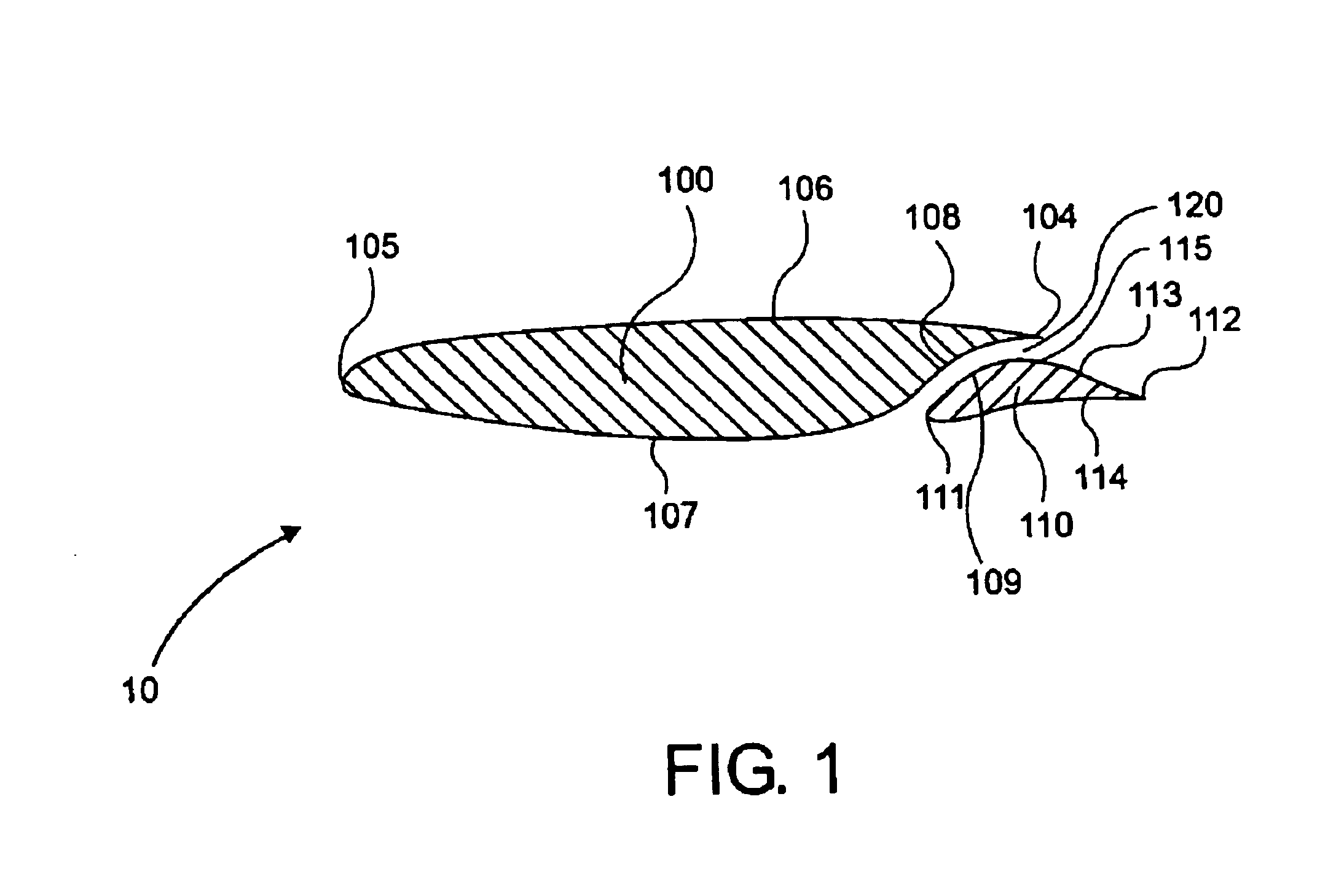
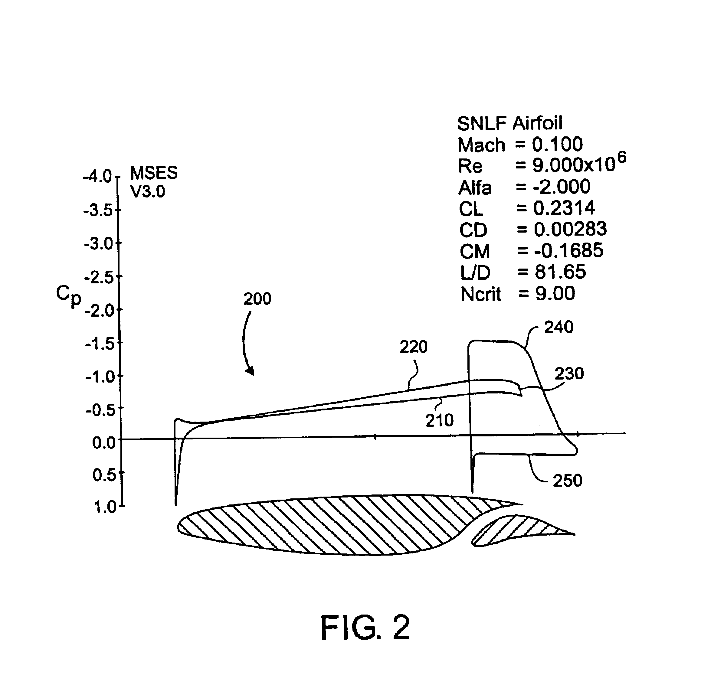
[0015]In accordance with the invention, there is provided an airfoil that includes a fore airfoil element. As here embodied, and depicted in FIG. 1, fore airfoil element 100 has an upper surface 106, a lower surface 107, a leading edge 105 and a trailing edge 104. Leading edge 105 provides a first contact between fore airfoil element 100 and the air surrounding the airfoil assembly 10. While the fore element of the airfoil depicted in FIG. 1 has a specific configuration, it is not the only airfoil configuration operable with the present invention. As will be set out below, rather than the invention being specific airfoil shapes, it is the interaction of the fore and aft elements of the airfoil, and their effect on the flow over and through the combined elements that provides the benefits of the invention. With the flow characteristics and pressure distri...


PUM


Abstract

An airfoil having a fore airfoil element, an aft airfoil element, and a slot region in between them. These elements induce laminar flow over substantially all of the fore airfoil element and also provide for laminar flow in at least a portion of the slot region. The method of the invention is one for inducing natural laminar flow over an airfoil. In the method, a fore airfoil element, having a leading and trailing edge, and an aft airfoil element define a slot region. Natural laminar flow is induced over substantially all of the fore airfoil element, by inducing the pressures on both surfaces of the fore airfoil element to decrease to a location proximate the trailing edge of the fore airfoil element using pressures created by the aft airfoil element.

Description

[0001]This invention was made with U.S. Government support under contract NAS1-01076, awarded by the National Aeronautics and Space Administration (NASA). The U.S. Government has certain rights in this invention.FIELD OF THE INVENTIONBackground of the Invention[0002]The present invention relates general airfoils, more particularly, to slotted airfoils. While airfoils can be used in a number of applications other than for the wings or control surfaces of aircraft, most applications for airfoils involve their use in aircraft wings in engine-driven aircraft. In such applications, the efficiency of the aircraft depends in large part on the drag forces impeding the passage of the aircraft through the air. Aircraft drag comprises, many components including: wing profile drag, induced drag, fuselage drag, empennage drag, cooling drag, nacelle drag, trim drag, and interference drag. Generally, the wing profile drag and the induced drag represent the largest contributions to the total aircra...

Claims


Application Information

Patent Timeline
Patent Type & Authority Patents(United States)
IPC IPC(8): B64C3/28B64C3/00B64C3/14
CPCB64C3/14B64C3/28Y02T50/12Y02T50/10
Inventor SOMERS, DAN M.
Owner AIRFOILS
Why Eureka
Try Eureka