Control valve flow adjustment device

a technology of flow adjustment and control valve, which is applied in the field of valves, can solve the problems of additional labor and additional time during which the valve cannot be used, and achieve the effect of precise control of flow characteristics

Inactive Publication Date: 2005-06-14
FISHER CONTROLS INT LLC
View PDF22 Cites 48 Cited by
  • Summary
  • Abstract
  • Description
  • Claims
  • Application Information

AI Technical Summary

Benefits of technology

[0005]An apparatus according to the invention is provided that limits the travel of the valve stem. This provides for a precise control over flow characteristics b

Problems solved by technology

Replacement of valve plugs and/or seat rings can necessitate disassembly and reassembly of the val

Method used


Image

  • Control valve flow adjustment device
  • Control valve flow adjustment device
  • Control valve flow adjustment device

Examples


Embodiment Construction

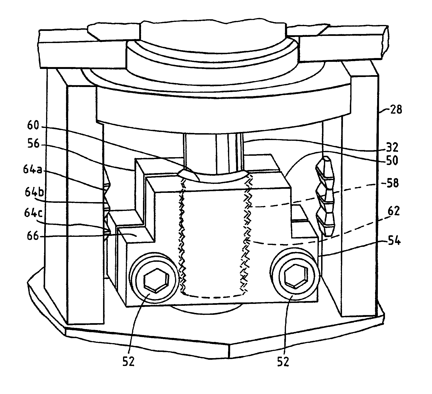
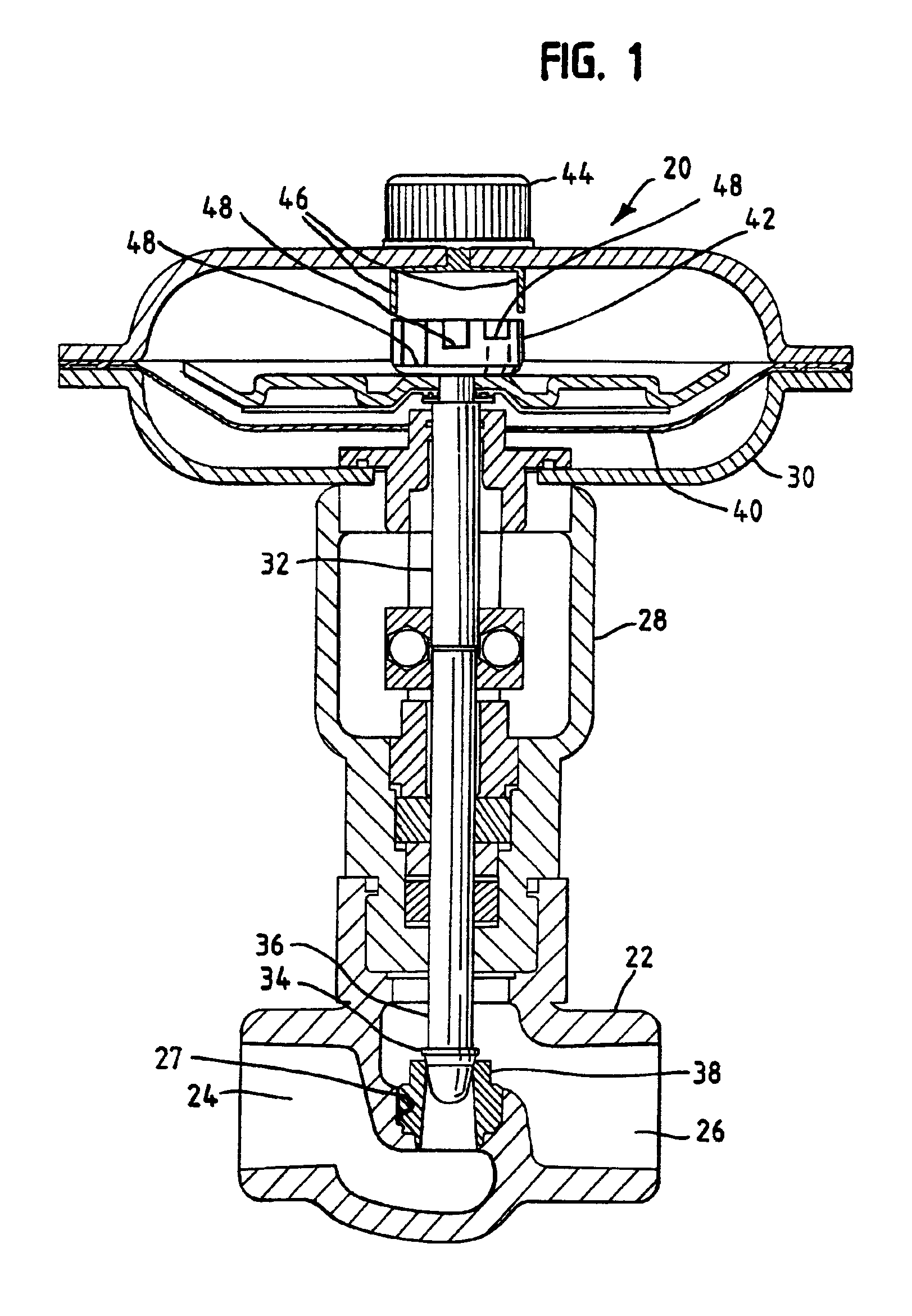
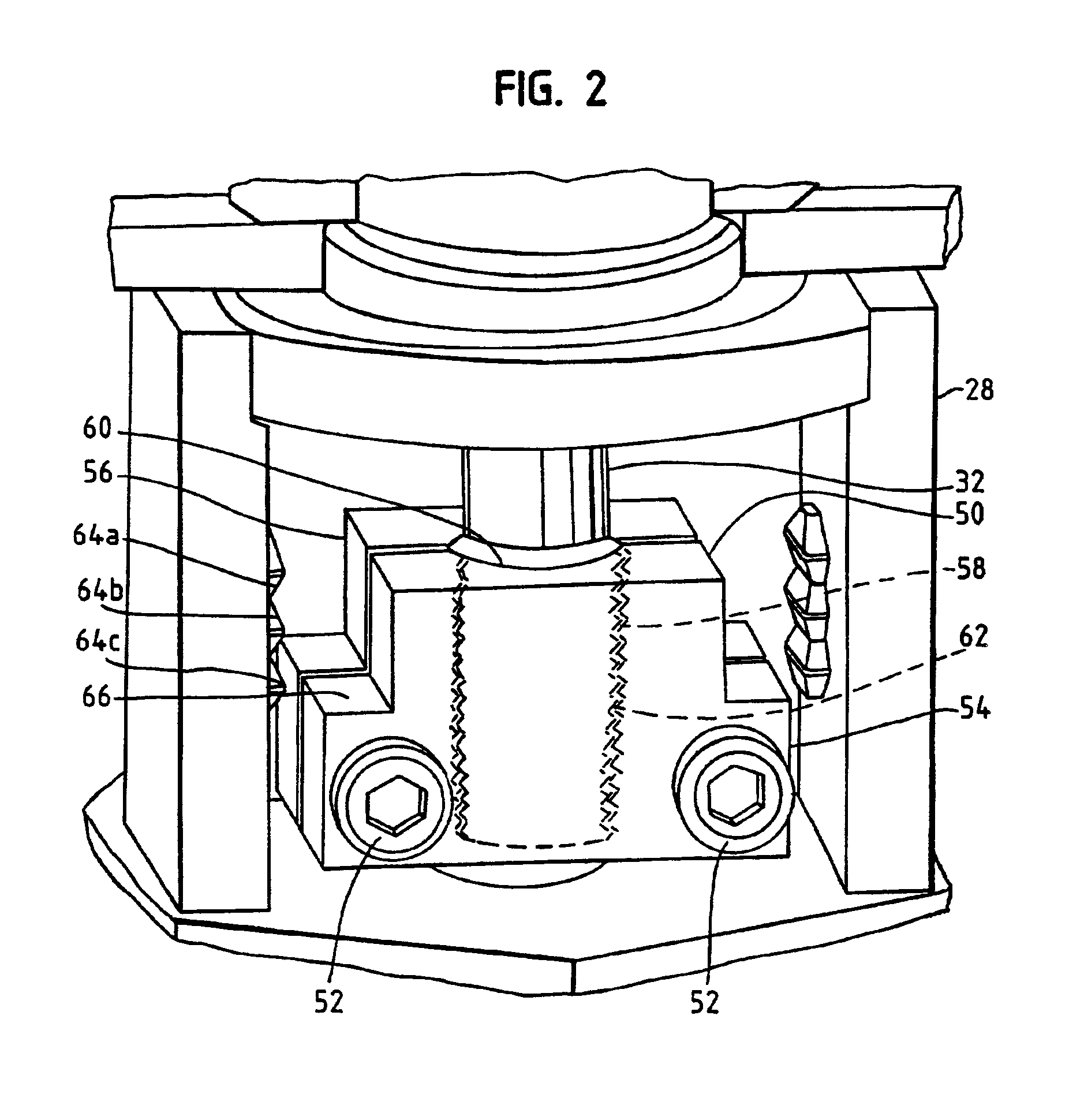
[0025]With reference initially to FIG. 1, a stem valve assembly 20 includes a valve body 22 that includes an outlet passage 24 and an inlet passage 26, an orifice 27 disposed between the outlet passage 24 and the inlet passage 26, a bonnet 28, and a diaphragm casing 30. (In an alternate example, the inlet passage 26 and the outlet passage 24 may be reversed, such that the fluid inlet passage becomes the fluid outlet passage, and the fluid outlet passage becomes the fluid inlet passage, thereby changing a downward flow valve to an upward flow valve.) A valve stem 32 extends through the diaphragm casing 30, the bonnet 28, and partially into the valve body 22. A valve plug 34 is attached to a lower end 36 of the valve stem 32, as oriented in FIG. 1. The valve plug 34 is sized and shaped to sealingly engage a valve seat 38 disposed within the orifice 27 within the valve body 22 when the valve assembly 20 is in a closed configuration. The valve stem 32 may be moved vertically in a known ...


PUM


Abstract

A valve includes a fluid inlet passage having a fluid inlet, a fluid outlet passage, an orifice between the fluid inlet passage and the fluid outlet, and a moveable valve plug adapted to move with respect to the orifice to vary the flow of fluid between the fluid inlet passage and the fluid outlet passage. A movable valve stem is attached to the valve plug and a travel limiting device is attached to the valve stem. The travel limiting device permits the valve to be placed in one of a plurality of desired flow configurations.

Description

RELATED APPLICATION[0001]This application claims the benefit of provisional application Ser. No. 60 / 335,626, filed Nov. 15, 2001, entitled “CONTROL VALVE FLOW ADJUSTMENT DEVICE.”FIELD OF THE INVENTION[0002]This invention relates generally to valves and more particularly to on / off valves, throttling valves and control valves having flow rate adjustment devices therein.DESCRIPTION OF THE RELATED ART[0003]Throttling valves, on / off valves and control valves are used in a wide number of process control system applications to control some parameter of a process fluid. While the process control system uses such a valve to ultimately control the pressure, level, pH or other desired parameter of a fluid, the valve basically controls the rate of fluid flow.[0004]Typically, an on / off valve, throttling valve, or control valve includes a fluid inlet passage coupled through an orifice to a fluid outlet passage and a closure member disposed in the orifice, which controls the amount of fluid flow t...

Claims


Application Information

Patent Timeline
IPC IPC(8): F15B15/00F15B15/24F16K1/32F16K1/52F16K21/16
CPCF15B15/10F16K1/523F15B15/24F15B1/24F15B15/264F16K1/52
Inventor HALL, RANDY J.BURR, RONALD C.STIEHL, MARK D.BURLAGE, BRIAN J.CARTWRIGHT, CARTER B.
Owner FISHER CONTROLS INT LLC
Why Eureka
Try Eureka