
Safety IV catheter infusion device

Inactive Publication Date: 2005-06-14
MILSTONE SCI
View PDF3 Cites 21 Cited by
  • Summary
  • Abstract
  • Description
  • Claims
  • Application Information

AI Technical Summary

Benefits of technology

[0016]A further objective is to provide a system that can be used easily by clinicians.
[0018]Briefly, the subject application pertains to a device for establishing an IV catheter by a clinician. The device includes a housing sized and shaped to fit in the hand of the clinician; a catheter assembly including a catheter member with a front portion adapted to be inserted into the vein of a patient; and a control member adapted to reciprocate the catheter assembly within said housing between a retracted position in which said catheter assembly is completely contained in said housing and an extended position in which said catheter member extends outwardly of said housing.A catheter member can be removably attached to the catheter assembly so that it can be removed in the extended position.

Problems solved by technology

More complex devices include fusion pumps that can deliver fluids to the patient at carefully metered rates using specific profiles.
However, these systems are not satisfactory for several reasons.
However, very often clinicians cannot find the proper vein or the proper infusion site on their first try.
Therefore, after the needle and catheter have been inserted, the whole system becomes contaminated.
However, obviously, this is a wasteful step.
However, this process requires two hands and is exactly the situation that subjects people to inadvertent needlesticks.
Another disadvantage of existing systems is that they normally require a linear or translational motion of the needle during insertion.
This is disadvantageous because it causes the needle to bend thereby causing pain to the patient.
Moreover, if the needle bends during insertion, it will miss the vein and the process has to be repeated.

Method used


Image

  • Safety IV catheter infusion device
  • Safety IV catheter infusion device
  • Safety IV catheter infusion device

Examples


Embodiment Construction

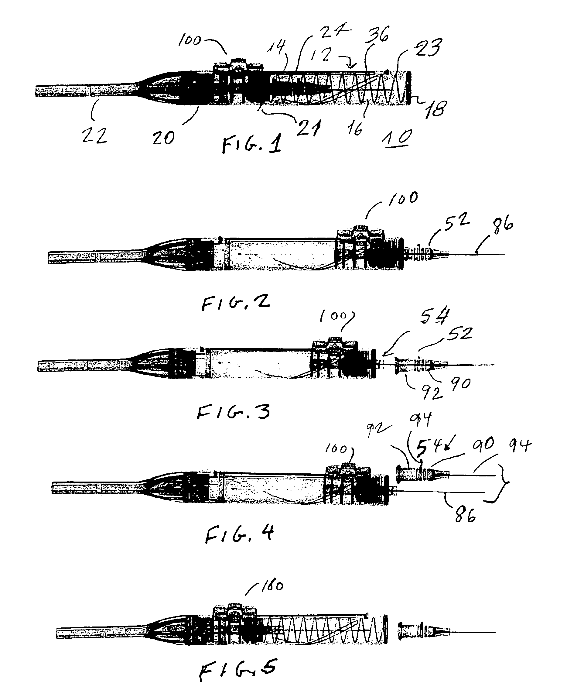
[0033]Referring now to the Figures, a device 10 constructed in accordance with this invention consists of a cylindrical housing or barrel 12 having an outer surface 14, an inner surface 16, a front end 18 and a rear end 20. An end piece 22 is attached to the rear end 20 of the barrel. The barrel 12 defines a cylindrical housing.

[0034]As shown in FIG. 1, a catheter assembly 21 is provided in the barrel 12. This catheter assembly is biased toward a retracted position by a biasing means such as a coil spring 23.

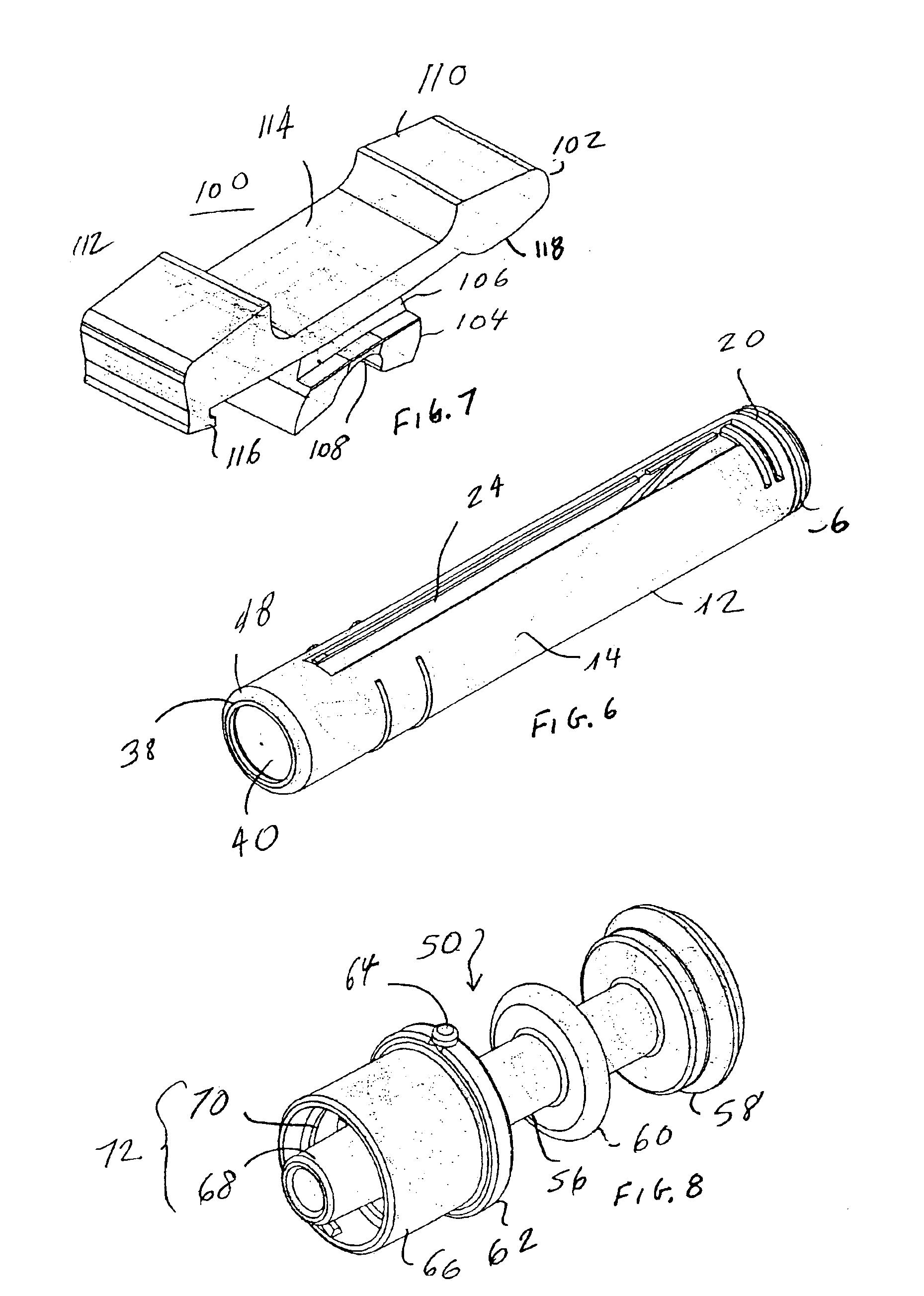
[0035]FIGS. 6 and 6A show more details of the barrel 12. It includes a longitudinal slot 24. The slot 24 is formed with two ledges 26 extending along the sides of the slot 24. These ledges terminate at a gap near the front end 18 to define a front key 28. In addition, gaps in the ledges 26 near the rear end 20 define a rear key 32. Two radial ribs 32A form an outer surface 14 of the barrel 12 to provide a better grip. At the rear end of the slot 24 a portion of the barrel is cut...


PUM


Abstract

A device for delivering an IV catheter to an IV infusion site is disclosed. The device includes a cylindrical housing adapted to fit into the hand of the clinician. A catheter assembly is disposed in the housing and can be advanced to an extended position and retracted. The catheter assembly includes a needle adapted to be inserted into the vein and the catheter is mounted on the needle to allow the catheter to be removed at will. The catheter assembly is rotated as the needle is inserted into the vein. Preferably the catheter assembly is rotated during the insertion of the needle and catheter. After the needle and catheter are inserted into the vein, the needle is retracted into the housing leaving the catheter in place. The housing and the needle can now be discarded.

Description

RELATED APPLICATIONS[0001]This application is a continuation to application Ser. No. 10 / 174,246 filed Jun. 18, 2002, now U.S. Pat. No. 6,726,658.BACKGROUND OF THE INVENTION[0002]a. Field of Invention[0003]This invention pertains to a device used to establish an IV catheter in a patient. More particularly, the invention pertains to a safety infusion device that includes a handpiece used to store and to selectively extend the IV catheter so that it can be introduced into the patient, the handpiece being constructed and arranged to insure that the IV catheter and the so-called underlying needle can be retracted into the barrel at will to protect clinicians from accidental needlesticks.[0004]b. Description of the Prior Art[0005]IV infusion is one of the most widely used procedures performed in hospitals and other healthcare provider sites. These infusions involve continuously injecting one or more liquids into the veins of a patient to achieve various results. Simple infusion systems ma...

Claims


Application Information

Patent Timeline
IPC IPC(8): A61M25/06A61M5/32
CPCA61M25/0631A61M5/3257A61M5/3271
Inventor HOCHMAN, MARK N.
Owner MILSTONE SCI
Learn More