Arc welding method

a technology of arc welding and arc welding, which is applied in the direction of arc welding equipment, manufacturing tools, welding equipment, etc., can solve the problems of reducing the appearance or finished quality of the welding portion and its surroundings, increasing the welding cost, and limiting the use quantity, so as to reduce the welding current

Inactive Publication Date: 2005-06-14
TOSHISADA YASUMURA
View PDF7 Cites 36 Cited by
  • Summary
  • Abstract
  • Description
  • Claims
  • Application Information

AI Technical Summary

Benefits of technology

[0007]An arc welding method according to the present invention is a method for subjecting a work to welding by the use of a welding wire. This arc welding method comprises the steps of: bringing the welding wire into contact with the work while applying a voltage between the welding wire and the work, thereby causing the end of the welding wire to be fixingly welded to the work; obtaining an electric resistance between the welding wire and the work during the contact between the welding wire and the work, so as to detect a minimum of the electric resistance; and significantly reducing the welding current by stopping the application of the voltage between the welding wire and the work after the detection of the minimum of the electric resistance.

Problems solved by technology

As a result, there is a danger that spatters generated on the work degrade the appearance or finished quality of the welding portion and its surroundings.
However, use of such gas induces an increase in welding cost, and further, the use quantity will be possibly restricted in the future from the viewpoint of environmental protection according to the kind of used gas.

Method used


Image

  • Arc welding method
  • Arc welding method
  • Arc welding method

Examples


Embodiment Construction

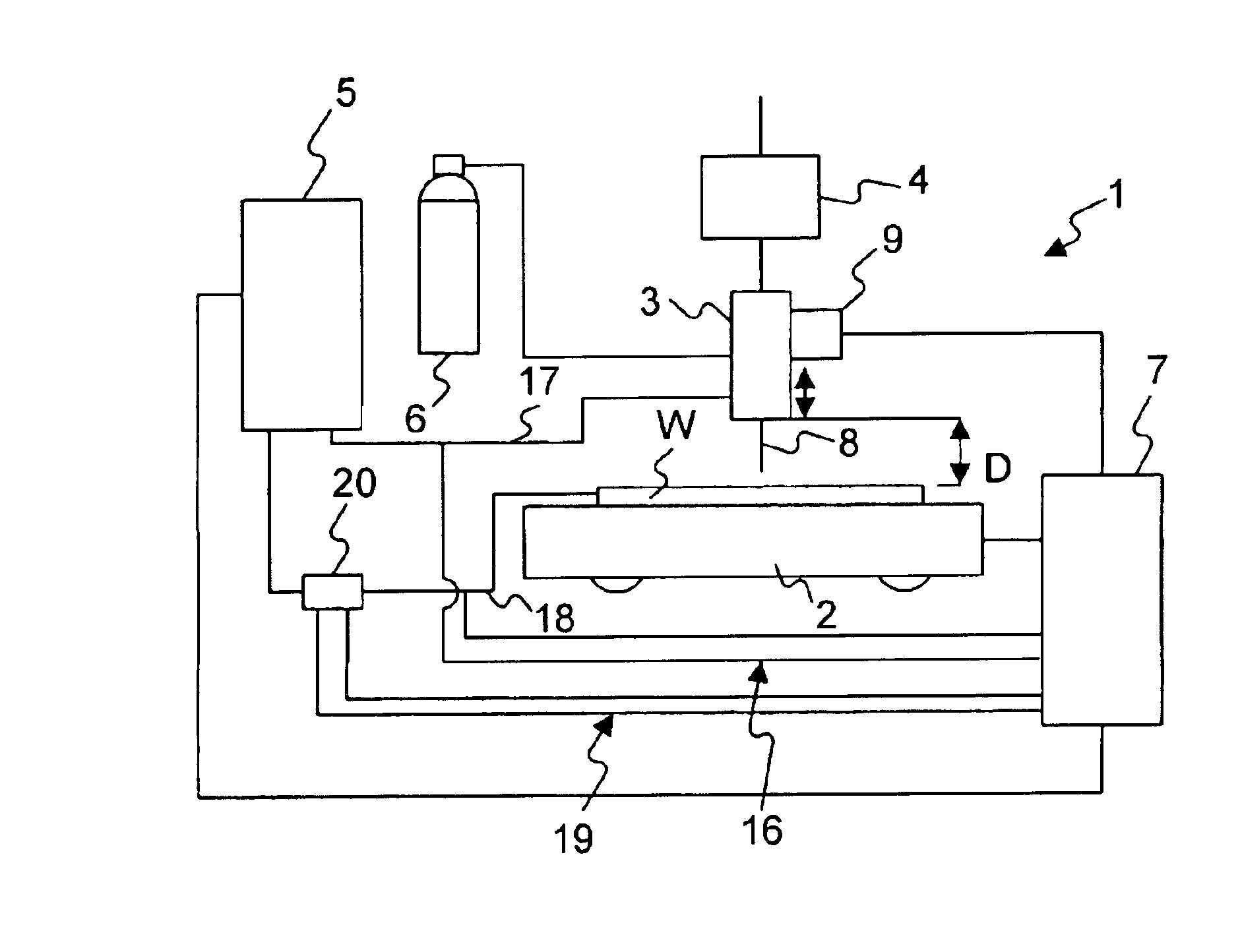
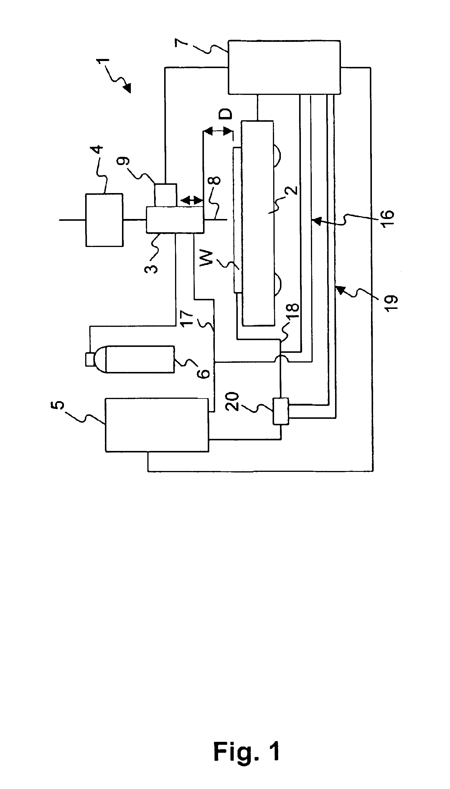
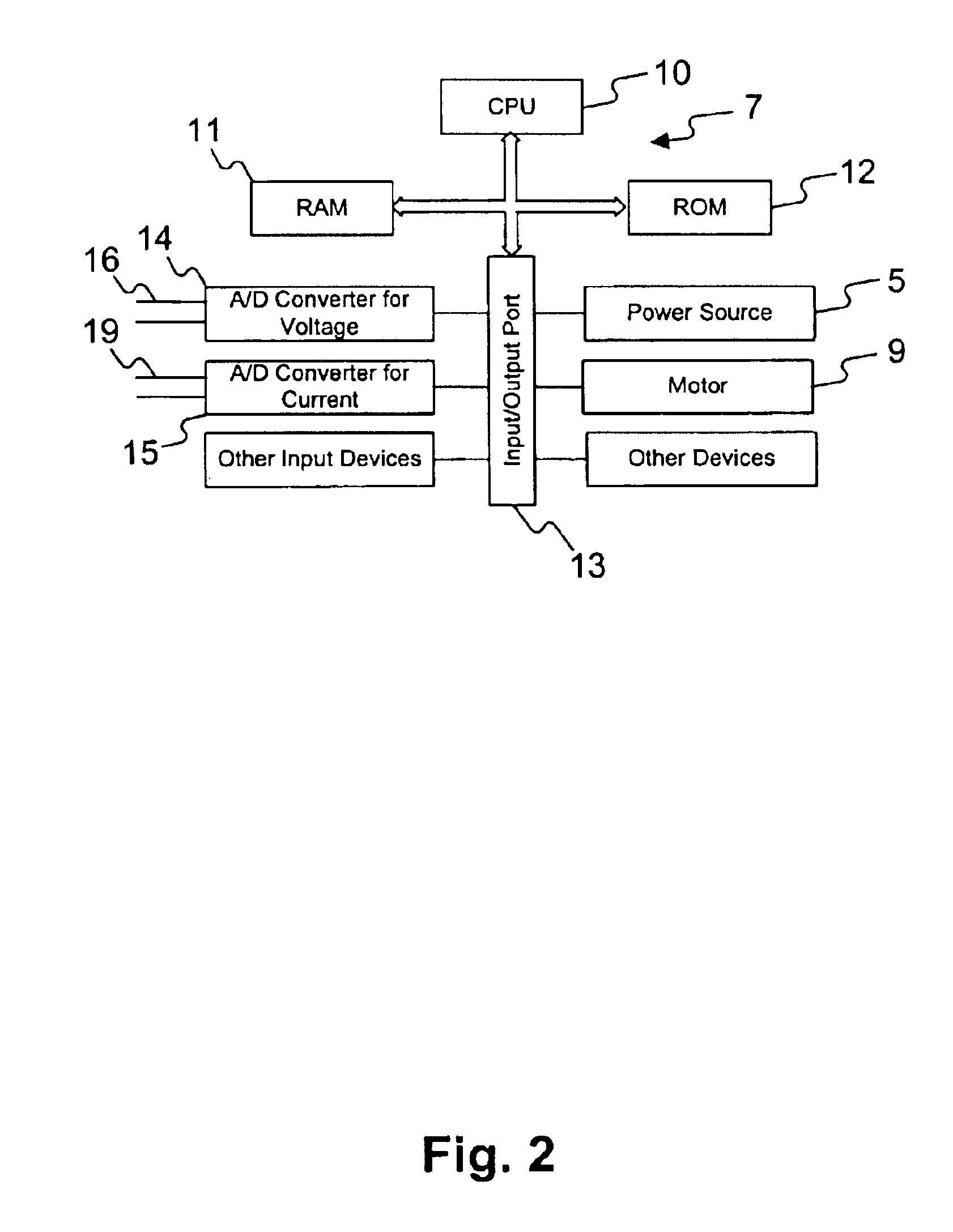
[0025]Referring to FIG. 1, a description will be given of a welding device which carries out a gas-metal arc welding method in a preferred embodiment according to the present invention. In FIG. 1, a gas-metal arc welding device 1 comprises mainly a carrier 2, a torch 3, a wire feeder 4, a power source 5, a shielding gas cylinder 6 and a controller 7.

[0026]The carrier 2 is adapted to mount thereon a work W to be welded, and it is configured in such a manner as to be moved in FIG. 1 by a moving device, not shown.

[0027]The torch 3 is disposed above the carrier 2, and holds therein a welding wire 8 for subjecting the work W to welding. The welding wire 8 held by the torch 3 extends downward in FIG. 1, i.e., toward the carrier 2, to thus face the work W mounted on the carrier 2. Here, the welding wire 8 is a metallic wire for welding, which is commercially available.

[0028]The above-described torch 3 is provided with a motor 9. The motor 9 serves to move the torch 3 in a vertical directio...


PUM

PropertyMeasurementUnit
timeaaaaaaaaaa
timeaaaaaaaaaa
voltageaaaaaaaaaa

Abstract

The present invention relates to an arc welding method in which generation of spatters can be suppressed while the use quantity of gas to be supplied to a welding portion can be decreased. A welding wire 8 is brought into contact with a work W while applying a voltage between the welding wire 8 and the work W, so that the end of the welding wire 8 is caused to be fixingly welded to the work W. At this time, an electric resistance between the welding wire 8 and the work W is continuously obtained during the contact between the welding wire 8 and the work W, and thus, a minimum of the electric resistance is detected. When the current is temporarily reduced after the detection of the minimum of the electric resistance, the tip of the welding wire 8 hardly bursts, thus suppressing the expelling of molten particles, which may cause spatters, from the welding wire 8. The minimum value is also used for the torch-to-workpiece distance control.

Description

RELATED APPLICATION[0001]This application is a continuation-in-part of prior application Ser. No. 09 / 869,018, filed Oct. 29, 2001, now abandoned which is a national phase entry under 35 U.S.C. § 371 from International Application No. PCT / JP98 / 05923, filed Dec. 24, 1998, in the European Patent Office, the contents of both of which are relied upon and incorporated herein by reference.TECHNICAL FIELD[0002]The present invention relates to a welding method and, more particularly, to an arc welding method in which a welding wire is used.BACKGROUND ART[0003]An arc welding method has been known as a method for subjecting a metallic work to welding. In this welding method, a welding wire is brought into contact with the work with application of a voltage between the welding wire and the work, so that the tip of the welding wire, which is fused by the energization at that time, is fixingly welded to the work. Thereafter, the welding wire is separated from the work in the state in which the ti...

Claims


Application Information

Patent Timeline
Patent Type & Authority Patents(United States)
IPC IPC(8): B23K9/095
CPCB23K9/095
Inventor KIM, YOU-CHULORSZAGH, PETER
Owner TOSHISADA YASUMURA
Why Eureka
Try Eureka