Remote wire feeder

a feeder and wire technology, applied in the field of remote wire feeders, can solve the problems of prone failure of the internal mechanical contactor of the arc powered feeder, damage to the mechanical contactor of the feeder, and inability to accommodate repeated use of extremely high welding currents, etc., to achieve high current, high duty cycle, and high power cycle

Inactive Publication Date: 2005-06-14
LINCOLN GLOBAL INC
View PDF5 Cites 76 Cited by
  • Summary
  • Abstract
  • Description
  • Claims
  • Application Information

AI Technical Summary

Problems solved by technology

However, the internal mechanical contactor in the arc powered feeder is prone to failure caused by arc damage to the contacts due to repeated switching of high inductance DC current.
Indeed, the mechanical contactor of the feeder is subject to damage from welding currents which often exceed the contactors current ratings.
It has been found that in some installations, the mechanical contactors do not accommodate repeated use of extremely high welding currents.
The wire feeder can not perform short, repetitive welds such as stitch welding or spot welding because of the accumulated heating of the contactor and the mechanical effect of repeated arcing of the contact in the mechanical contactor.
These remote wire feeders have difficulty in changing voltage.
These units have a single cable between the power source and the wire feeder since coaxial cables and other dual cable designs are extremely expensive.

Method used


Image

  • Remote wire feeder
  • Remote wire feeder

Examples


Embodiment Construction

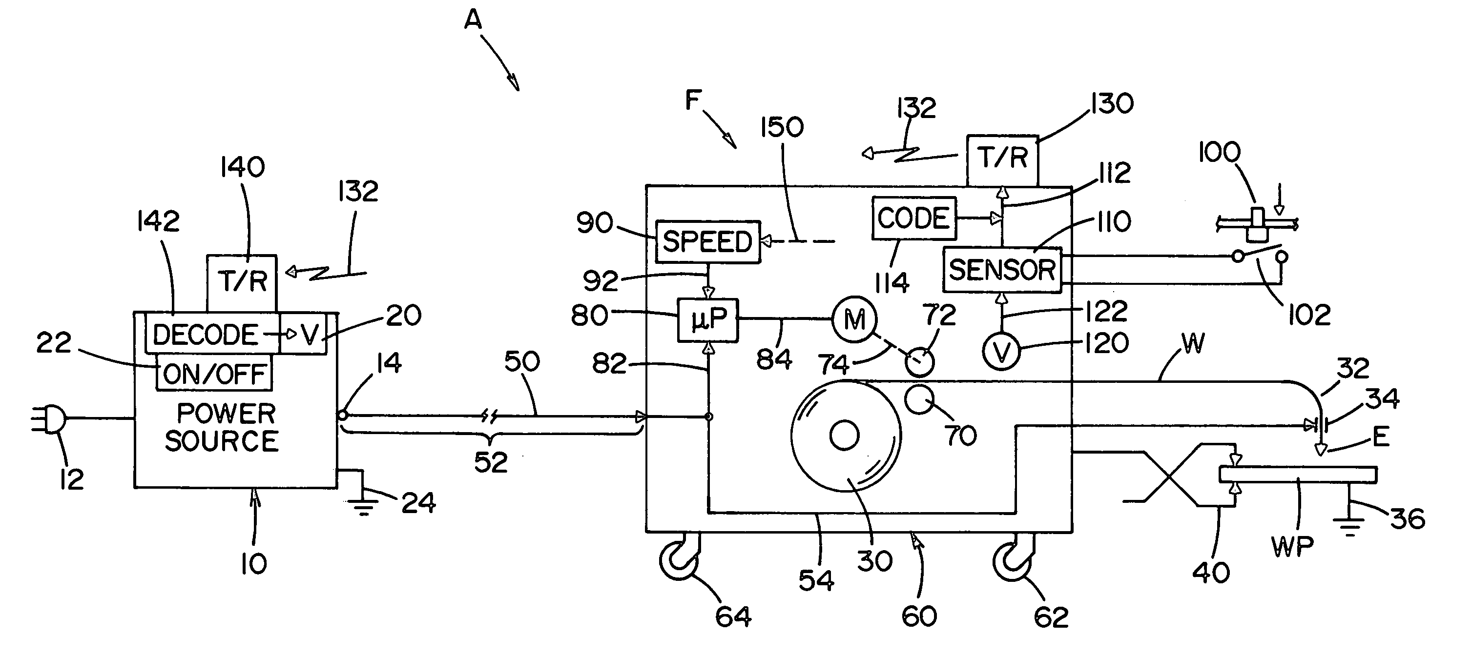
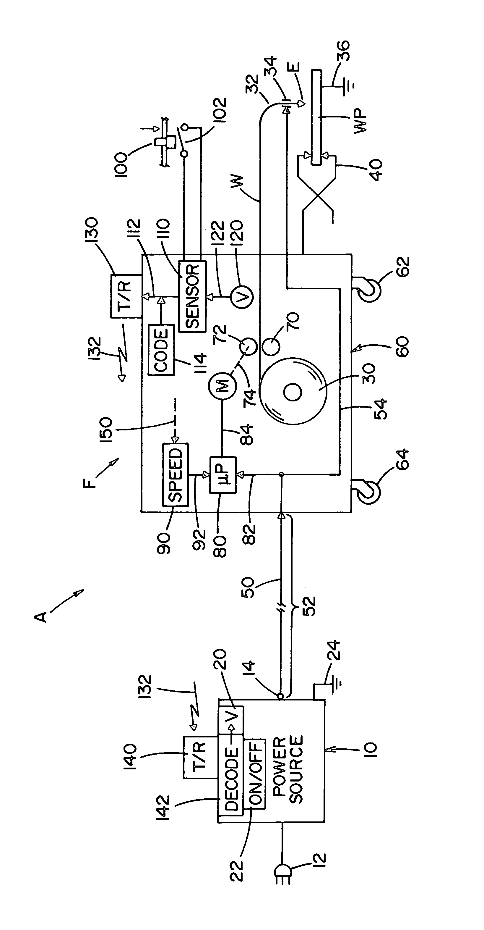
[0009]The single drawing shows an electric arc welder A of the type including a generally fixed power source and having input 12 and output terminal or output 14 wherein the arc voltage is controlled by a circuit when the power supply is on at switch 22. In accordance with normal practice, power source 10 has ground 24. The invention involves a remotely located wire feeder F of the type including an internal spool 30 for electric arc welding wire W. The wire is pulled from spool 30 and pushed through gun or torch 32 to a contact sleeve 34. Electric power is directed to electrode E, which is wire W, for performing an electric arc welding process between the electrode and workpiece WP. Standard ground 36 is connected to the wire feeder through ground clamp 40. Input cable 50 has a length 52 and connects terminal 14 to power lead 54 within feeder F so power is directed to contact sleeve 34 for the welding process when switch 22 of the power supply is closed. In the prior art, a mechani...


PUM

PropertyMeasurementUnit
welding currentaaaaaaaaaa
arc voltageaaaaaaaaaa
voltageaaaaaaaaaa

Abstract

A wire feeder including a motor driving a set of feed rolls to force a welding wire from a spool through a welding torch to a welding operation. The wire feeder has an input lead to be connected to the output terminal of a remotely located power source having an on condition and an off condition where a welding current is directed to the output terminal only when the source is in the on condition. A weld starting trigger with a weld start position located adjacent the torch closes a switch when the trigger is shifted to the weld position, a circuit senses when the switch is closed, and a transmitter on the wire feeder transmits a start signal to the power source when the trigger switch is closed whereby the power source is shifted to its on condition when the trigger is in the weld position.

Description

[0001]The present invention relates to the art of electric arc welding and more particularly to a wire feeder with remote control for directing power to the feeder and to the arc.BACKGROUND OF INVENTION[0002]In many welding applications, a power source is in a fixed location and provides arc power through an electrode cable to a remotely located wire feeder having a spool of welding wire driven by a pair of feed rolls through an elongated tube out a welding torch to the welding operation. Current is directed through the electrode cable to the remotely located wire feeder that is movable from position to position for accommodating welding at different locations. The power on the electrode cable drives the motor that rotates feed rolls for pulling wire from the spool and forcing it through the gun or torch. A trigger on the gun or torch closes a switch to initiate the welding operation and start the drive motor for feeding wire. In accordance with this technology, the electrode cable ...

Claims


Application Information

Patent Timeline
Patent Type & Authority Patents(United States)
IPC IPC(8): B23K9/12
CPCB23K9/124
Inventor ZUCKER, JAMES P.CLARK, KEITH L.
Owner LINCOLN GLOBAL INC
Why Eureka
Try Eureka