
System for controlling the temperature of an aircraft airfoil component

Inactive Publication Date: 2005-06-14
HAMILTON SUNDSTRAND CORP +1
View PDF10 Cites 29 Cited by
  • Summary
  • Abstract
  • Description
  • Claims
  • Application Information

AI Technical Summary

Benefits of technology

[0010]According to one implementation of this invention a resistive heater element is secured to the airfoil surface so that the heating element is able to warm the surface as needed. A controller controls the operation of the heater element. A plurality of detectors are associated with corresponding portions of the heater element to provide the controller with information regarding the resistance of the corresponding portions. The controller uses the resistance information to determine a temperature of each of the corresponding portions. By monitoring the temperature of each of the portions, accurate information regarding the entire heating element becomes available to monitor the quality of operation of the heater element.
[0011]In one example, the resistive heater ele

Problems solved by technology

One issue that is presented repeatedly on aircraft is the potential for ice formation on portions of the aircraft such as the wings.
Obviously, when the heating elements are not operating as desired, the potential for ice build up exists.
Three basic problems that can occur is that heat is applied when it should not be, heat is not applied when it should be and that heat is unevenly applied even though heat is needed across the entire component.
An electrical heating system that fails to operate as required typically is experiencing an electrical short or an open circuit within the heater, itself.
Because of the size of a typical heating arrangement, detecting a short or open within the circuit does not adequately pinpoint the identification of a problem.
Moreover, the time-consuming technique and the expensive equipment required make this approach less than ideal in many situations.

Method used


Image

  • System for controlling the temperature of an aircraft airfoil component
  • System for controlling the temperature of an aircraft airfoil component

Examples


Embodiment Construction

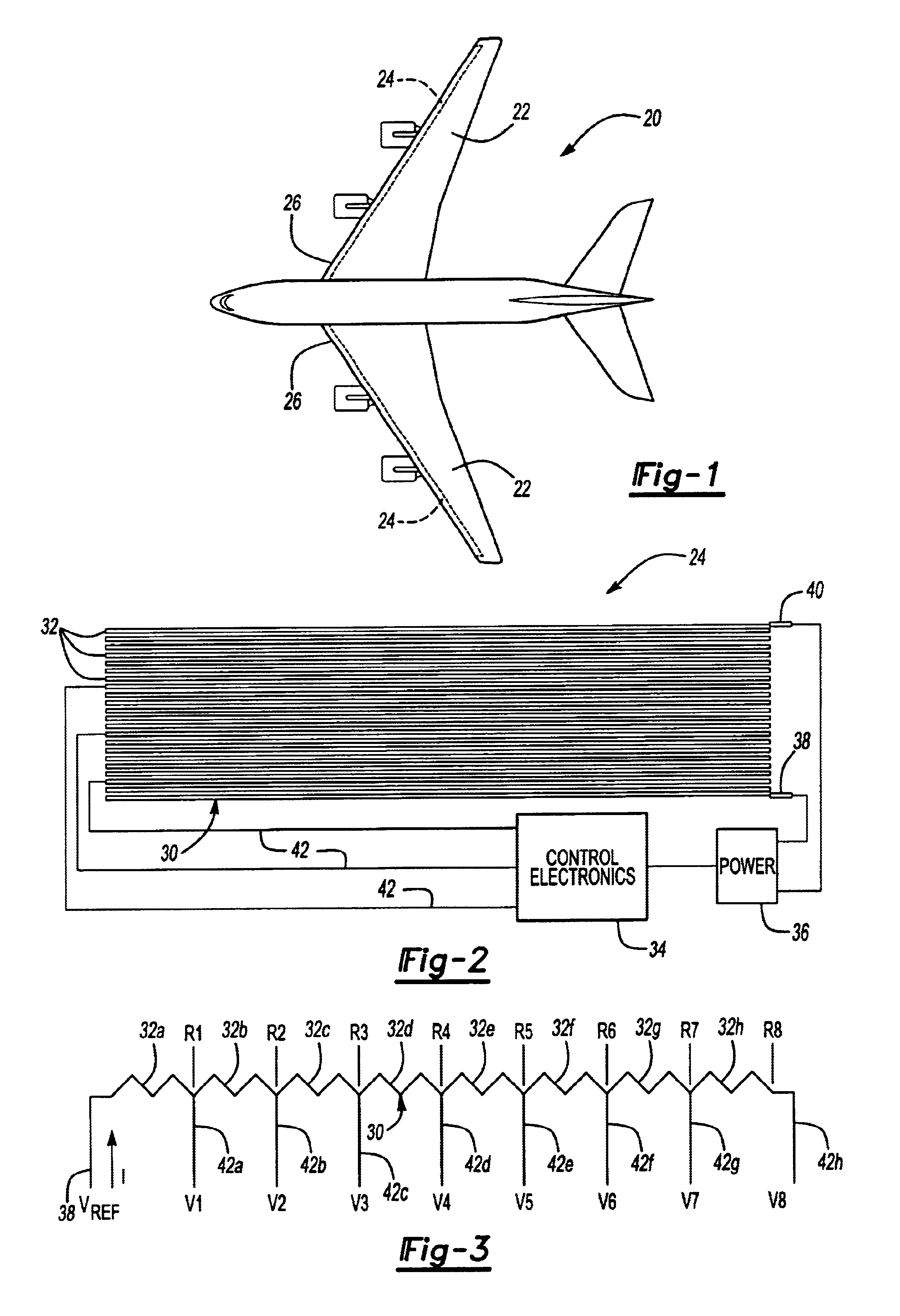
[0017]FIG. 1 schematically illustrates an aircraft 20 having wings 22. Electrical resistive heater devices 24 are supported on the body of the wings 22 near a leading edge 26. Although this description utilizes the wings 22 as example airfoil components incorporating a system designed according to this invention, the invention is not so limited. Those skilled in the art who have the benefit of this description will appreciate the use of this invention for a variety of airfoil components such as fins, propeller blades, etc. on a variety of aircraft, for example.

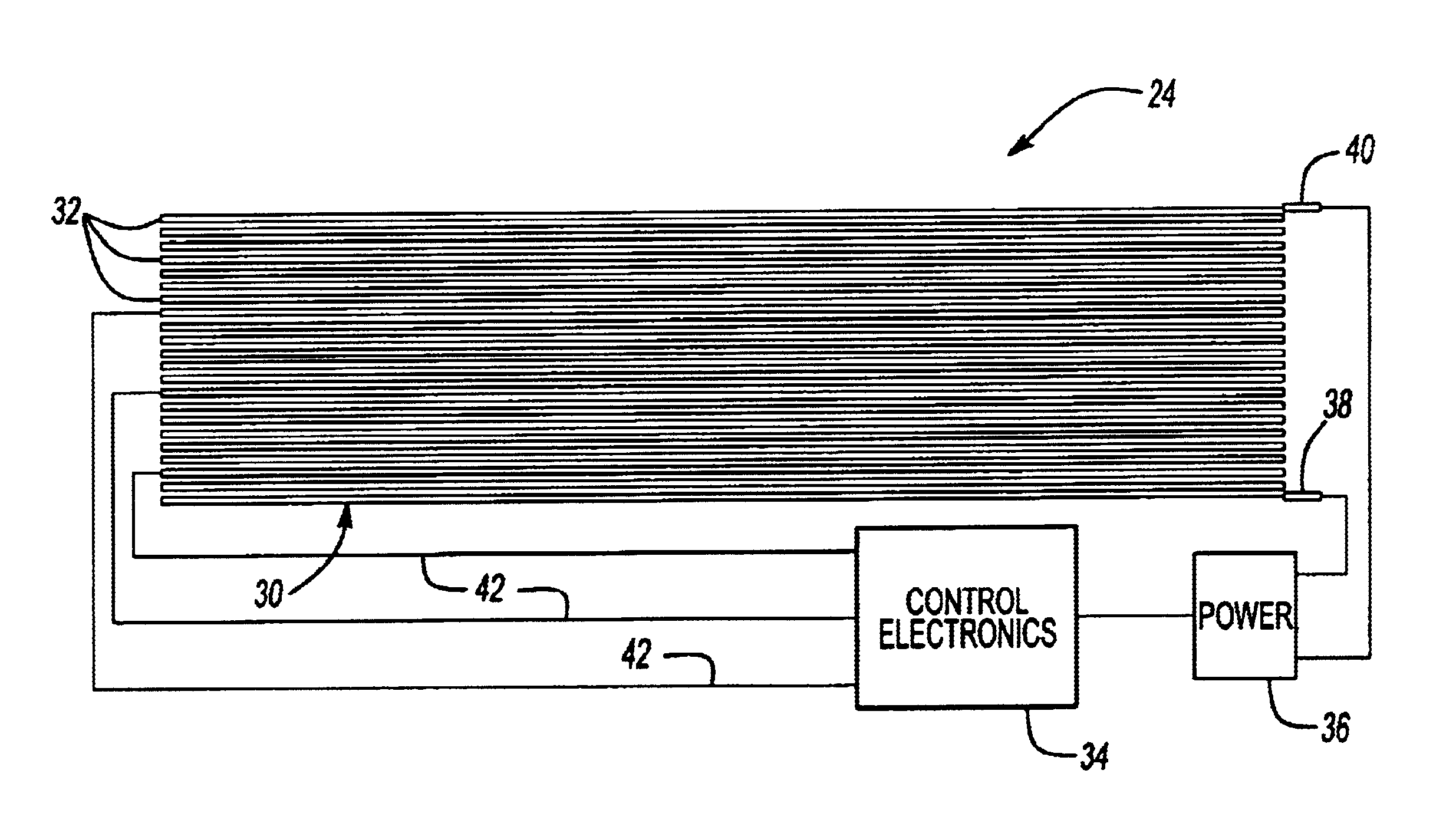
[0018]The resistive heater devices 24 in this example each include a resistive heater element 30. As schematically shown in FIG. 2, the resistive heater element 30 may comprise a wound conductive wire or an etched foil layer that can be laminated onto a surface of the airfoil component using conventional lamination techniques. In the example of FIG. 2, the resistive heater element 30 includes a plurality of windings 32 of a co...


PUM


Abstract

An airfoil temperature control arrangement includes a resistive heater element. A plurality of detectors allow a controller to gather resistance information at various intervals along the resistive heater element. Determining the resistance of the corresponding portions of the heater element allows the controller to utilize a known relationship between resistance and temperature for the material selected to make the resistive heater element. In one example, a nickel alloy or other material having a high coefficient of resistance is chosen to provide the controller with the ability to determine a temperature for each portion of the heater element. The determined temperature information is used, for example, to monitor whether any portion of the heater element has become delaminated from the airfoil surface.

Description

CROSS REFERENCE TO RELATED APPLICATIONS[0001]This application claims priority to U.S. Provisional Patent Application No. 60 / 404,341 filed Aug. 19, 2002.FIELD OF THE INVENTION[0002]This invention generally relates to controlling the temperature on a surface of an aircraft airfoil component. More particularly, this invention relates to monitoring and controlling the operation of a resistive heating element used to heat a surface on an airfoil componentDESCRIPTION OF THE PRIOR ART[0003]One issue that is presented repeatedly on aircraft is the potential for ice formation on portions of the aircraft such as the wings. Conventional approaches include heating the wings to prevent ice formation or to shed ice that has already formed. Obviously, when the heating elements are not operating as desired, the potential for ice build up exists.[0004]There are two basic approaches in the industry for heating airfoil components including bleed air systems and using electrical heating elements. Simil...

Claims


Application Information

Patent Timeline
IPC IPC(8): G01K1/00G01K1/02
CPCG01K1/026
Inventor GOLDBERG, JOSHUA I.HOLBROOK, RANDY P.
Owner HAMILTON SUNDSTRAND CORP
Features
  • Generate Ideas
  • Intellectual Property
  • Life Sciences
  • Materials
  • Tech Scout
  • Unparalleled Data Quality
  • Higher Quality Content
  • 60% Fewer Hallucinations
Learn More