Power plant operation control system and a power plant maintaining and managing method

Inactive Publication Date: 2005-06-14
MITSUBISHI HITACHIPOWER SYST LTD
View PDF28 Cites 13 Cited by
  • Summary
  • Abstract
  • Description
  • Claims
  • Application Information

AI Technical Summary

Problems solved by technology

However, these technologies are all related to processing in the inside of a power generating facility such as instructions of operations, provision of work information, and so on and do not include centralized control and management of a plurality of power generating facilities.

Method used


Image

  • Power plant operation control system and a power plant maintaining and managing method
  • Power plant operation control system and a power plant maintaining and managing method
  • Power plant operation control system and a power plant maintaining and managing method

Examples


Embodiment Construction

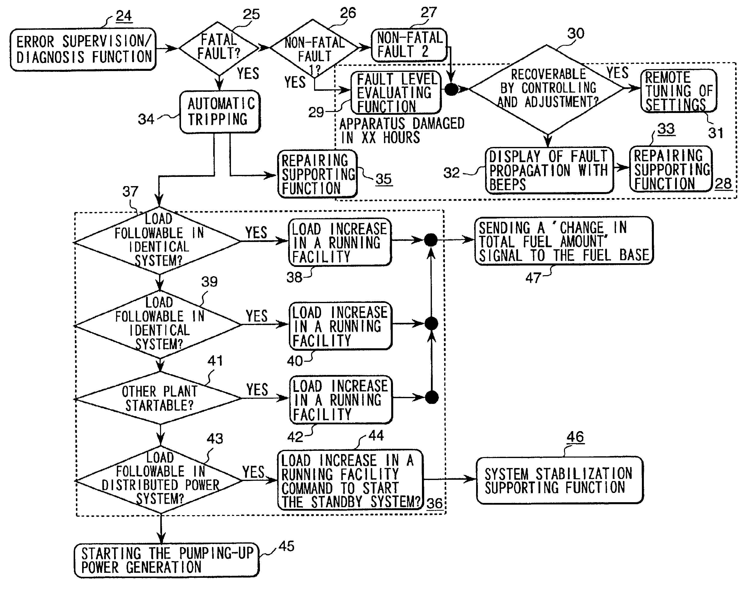
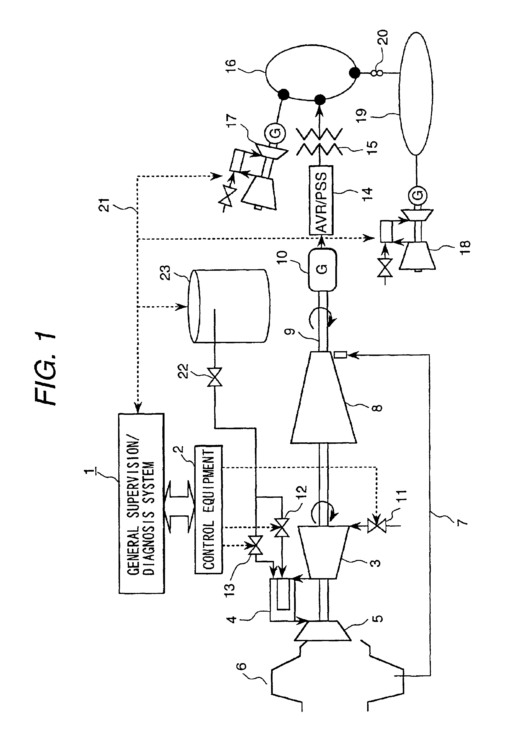
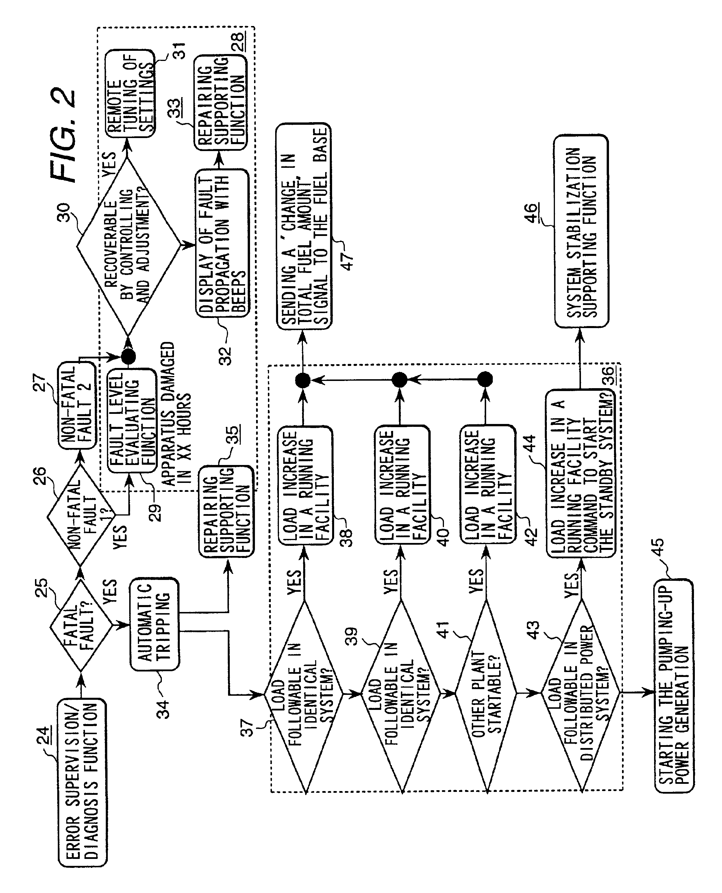
[0018]FIG. 1 shows a power supplying system comprising a plurality of power generating facilities which include a distributed power supply group which is an embodiment of the present invention. Below will be explained the present invention using the application to an arbitrary gas turbine combined power generating facility as an example.

[0019]Referring to FIG. 1, the system comprises a general supervision / diagnosis system 1 for managing a power supply system and a piece of control equipment 2 which supplies process quality information of a selected power generating facility to the diagnosing system 1.

[0020]One of the power generating facilities is linked to a power system through a power regulator which regulates the voltage and power fluctuation of power generated by a generator 10 and a transformer 15 which regulates power from the power regulator 14 into a voltage for the power system 16.

[0021]One of said power generating facilities consists of a compressor 3 which compresses air...


PUM


Abstract

Quick recovery or recovery support of a faulty power generating facility by real time diagnoses such as facility failure diagnosis, supervision for failure symptoms, facility diagnosis by evaluation of performance using databases between the power generating facilities and an operation control system. The operation control system transfers information on operating status and secular characteristic changes of apparatus from power generating facilities or information from operators of selected power generating facilities. The level of a failure of a power generating facility which has a failure is evaluated and repairing information (e.g. recovery procedures, processes, required parts, inventory of the parts, possible failure causes, etc.) is automatically created from repairing information prepared in advance for each evaluation condition. The repairing information is then sent to the operation supporting section of the power generating facility.

Description

BACKGROUND OF THE INVENTION[0001]1. Field of the Invention[0002]The present invention relates to an operation control system and a maintaining and managing method for power generating facilities fit for maintenance / management services of a power network group consisting of a plurality of power supplying facilities.[0003]2. Related Background Art[0004]Technologies on management of power generating facilities have been disclosed in Japanese Non-examined Patent Publications No. 10-301621 (1998), No. 11-3113 (1999), No. 7-152984 (1995), and No. 5-284252 (1993).[0005]However, these technologies are all related to processing in the inside of a power generating facility such as instructions of operations, provision of work information, and so on and do not include centralized control and management of a plurality of power generating facilities.[0006]Real time diagnoses of a plurality of power generating facilities such as facility failure diagnosis, supervision for failure symptoms, facili...

Claims


Application Information

Patent Timeline
Patent Type & Authority Patents(United States)
IPC IPC(8): G05B13/04G05B23/02G06Q50/00G06F3/14G06Q50/06G06Q50/10H04Q9/00
CPCG05B13/042G05B23/0254G05B23/027G05B23/0289H02M3/00G05B23/0291Y10S715/963H02J2003/001Y02E20/16H02J3/001H02J3/004Y04S10/52
Inventor NAGAFUCHI, NAOYUKIIWAI, YASUSHIIKEDA, HIRAKU
Owner MITSUBISHI HITACHIPOWER SYST LTD
Why Eureka
Try Eureka