Bus system for use with information processing apparatus

a technology for information processing apparatus and bus system, which is applied in the direction of electric digital data processing, instruments, etc., can solve the problems of system processor bus utilization efficiency deterioration, and achieve the effect of maximum utilization efficiency

Inactive Publication Date: 2005-06-14
HITACHI LTD
View PDF23 Cites 16 Cited by
  • Summary
  • Abstract
  • Description
  • Claims
  • Application Information

AI Technical Summary

Benefits of technology

[0006]It is therefore an object of the present invention to provide a bus system for use with an information processing apparatus capable of maximizing the utilization efficiency of each bus.
[0009]Still another object of the present intention is to provide a bus system for use with an information processing apparatus in which when there is established an interconnection between at least three buses including three kinds of buses i.e. system, memory, and processor buses, the utilization efficiency of each bus can be maximized.
[0017]As a result, it is possible to develop the maximum utilization efficiency for each of the three kinds of buses.

Problems solved by technology

In the former constitution, during a cooperative action of the system and memory buses, namely, during the so-called direct memory access (DMA), the processor bus cannot operate in an independent fashion, which consequently leads to a deterioration of the utilization efficiency of the processor bus.
In the latter case, on the other hand, during a cooperative operation of the processor and memory buses i.e. during the so-called main memory access, the system bus cannot operate in an independent manner, thereby leading to a problem of a deterioration of the utilization efficiency of the system bus.

Method used


Image

  • Bus system for use with information processing apparatus
  • Bus system for use with information processing apparatus
  • Bus system for use with information processing apparatus

Examples


first embodiment

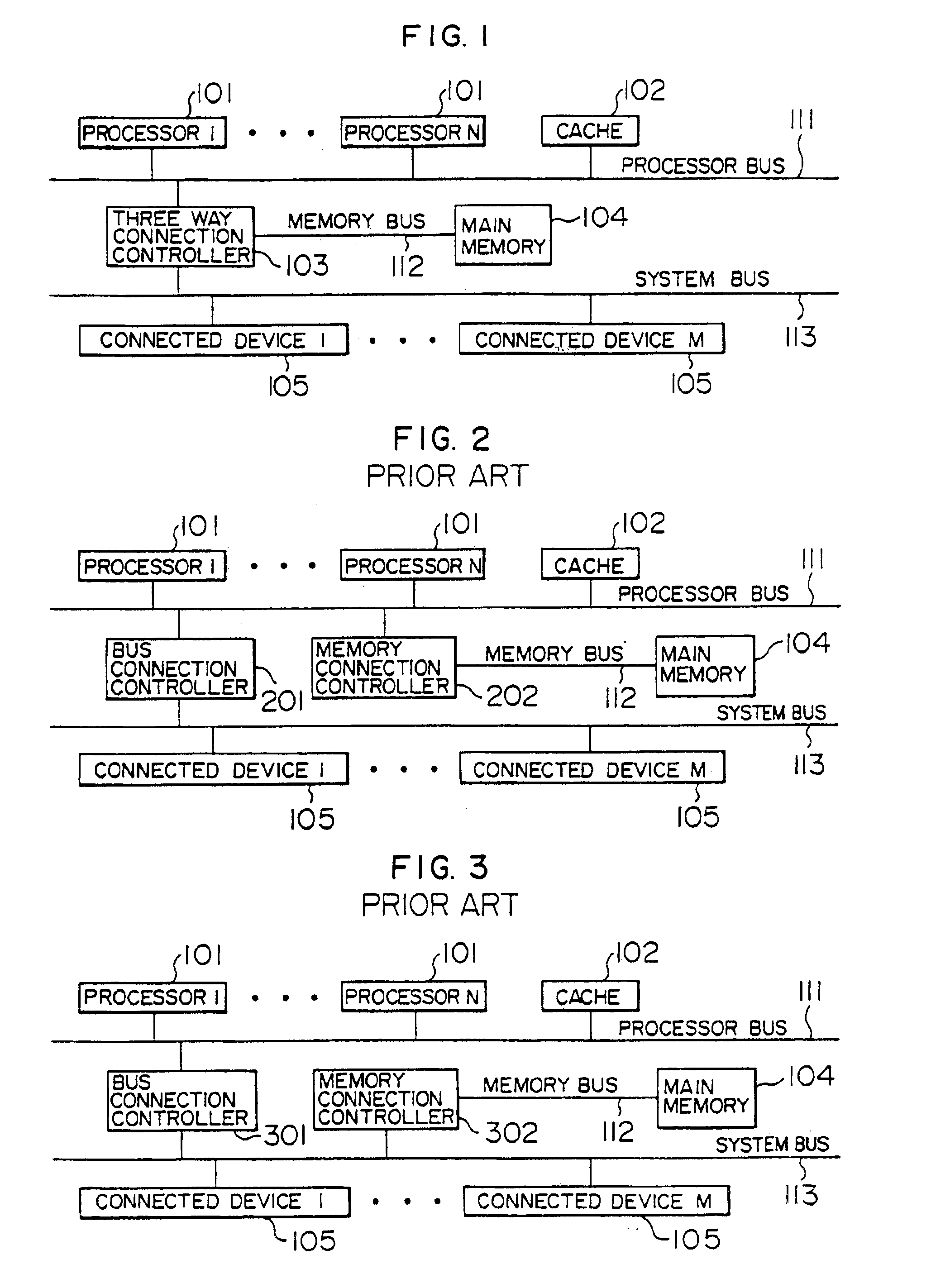
[0031]First, the present invention will be described with reference to FIGS. 1 to 6. In this regard, FIGS. 2 and 3 show configurations of a bus system in the conventional technology, which will be described here in detail for comparison with the present invention.

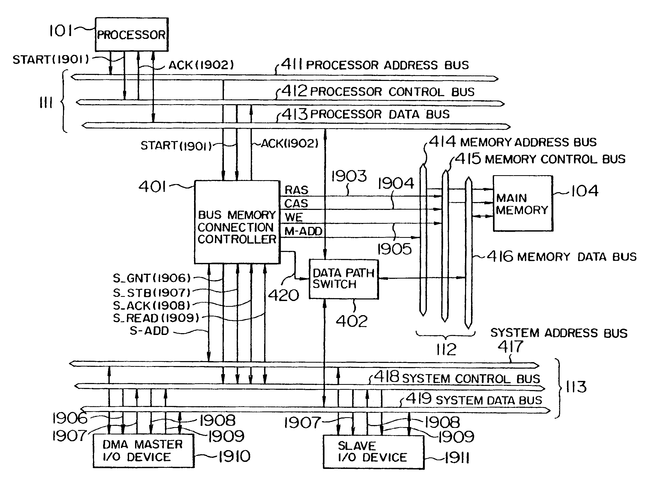
[0032]In each of FIGS. 1 to 3, there are disposed processors 101 (n processors; where, n is an integer) a cache memory system 102, a main memory 104, and system bus connection devices 105 (M devices; where, M is an integer). The connected devices 105 may be so-called I / O devices such as a controller for disk files, a controller for drawing and for displaying images, and a controller for networks and communications. Reference numerals 111, 112, and 113 denote a processor bus, a memory bus, and a system bus, respectively. In FIG. 1, a numeral 103 designates a three-way connection controller. In FIGS. 2 and 3, numerals 201 and 301 respectively correspond to bus connection controllers 201 and 301 and memory connection controlle...

second embodiment

[0045]In the present invention shown in FIG. 7, four buses including three kinds of buses i.e. the two processor buses 711 and 712, the memory bus 112, and the system bus 113 are connected to form a four-way connection by the four-way connection controller 705. The processors 701 and 703 are single-type processors to which the cache memory systems 702 and 704 can be respectively connected. In consequence, although the processors 701 and 703 can directly access the separate cache memories 702 and 704 respectively without using the processor buses, the processor buses cannot be shared therebetween.

[0046]In FIG. 7, the four-way connection controller 705 accomplishes the connection control between four buses including three types of buses such that, for example, a communication between the processors 701 and 703 is achieved in concurrence with a DMA operation or a main memory access from the processor 701 and a system bus access from the processor 702 are concurrently executed. With the...


PUM


Abstract

A processor bus linked with at least a processor, a memory bus linked with a main memory, and a system bus linked with at least an input / output device are connected to a three-way connection control system. The control system includes a bus-memory connection controller connected to address buses and control buses respectively of the processor, memory, and system buses to transfer address and control signals therebetween. The control system further includes a data path switch connected to data buses respectively of the processor, memory, and system buses to transfer data via the data buses therebetween depending on the data path control signal.

Description

[0001]This is a continuation application of Ser. No. 09 / 983,373, filed Oct. 24, 2001 (now U.S. Pat. No. 6,810,461); which is continuation application of Ser. No. 09 / 690,998, filed Oct. 18, 2000 (now U.S. Pat. No. 6,334,164); which is a continuation application of U.S. Ser. No. 09 / 518,696, filed Mar. 3, 2000 (now U.S. Pat. No. 6,195,719); which is a continuation application of U.S. Ser. No. 09 / 375,356, filed Aug. 17, 1999 (now U.S. Pat. No. 6,098,136); which is a continuation application of U.S. Ser. No. 09 / 276,968 filed on Mar. 26, 1999 (now U.S. Pat. No. 6,006,302); which is a continuation application of U.S. Ser. No. 09 / 143,985, filed Aug. 31, 1998 (now U.S. Pat. No. 5,935,231); which is a continuation application of U.S. Ser. No. 08 / 959,913, filed Oct. 29, 1997 (now U.S. Pat. No. 5,889,971); which is a continuation application of U.S. Ser. No. 08 / 601,993, filed Feb. 15, 1996, (now U.S. Pat. No. 5,751,976); which is a continuation application of U.S. Ser. No. 08 / 449,088, filed May...

Claims


Application Information

Patent Timeline
Patent Type & Authority Patents(United States)
IPC IPC(8): G06F13/40
CPCG06F13/4027G06F13/4022
Inventor OKAZAWA, KOICHIKIMURA, KOICHIKAWAGUCHI, HITOSHIABURANO, ICHIHARUKOBAYASHI, KAZUSHIMOCHIDA, TETSUYA
Owner HITACHI LTD
Why Eureka
Try Eureka