Heat exchanger panel

a heat exchanger and panel technology, applied in the direction of lighting and heating apparatus, combustion process, stationary conduit assemblies, etc., can solve the problems of heavy, difficult inspection, heavy old heat exchangers, and inability to be removed for inspection or replacement, etc., to achieve less complex, less expensive to manufacture, and light weight

Inactive Publication Date: 2005-06-21
AEROJET ROCKETDYNE INC
View PDF22 Cites 26 Cited by
  • Summary
  • Abstract
  • Description
  • Claims
  • Application Information

AI Technical Summary

Benefits of technology

[0004]Accordingly, it is an object of the present invention to provide a heat exchanger panel which is less complex, lighter, and less expensive to manufacture.

Problems solved by technology

This method required the use of expensive and high density (heavy) metal tubes which could not be removed for inspection or replacement.
As a result, these old heat exchangers were heavy, costly, difficult to inspect, and virtually impossible to maintain.

Method used


Image

  • Heat exchanger panel
  • Heat exchanger panel
  • Heat exchanger panel

Examples


Embodiment Construction

)

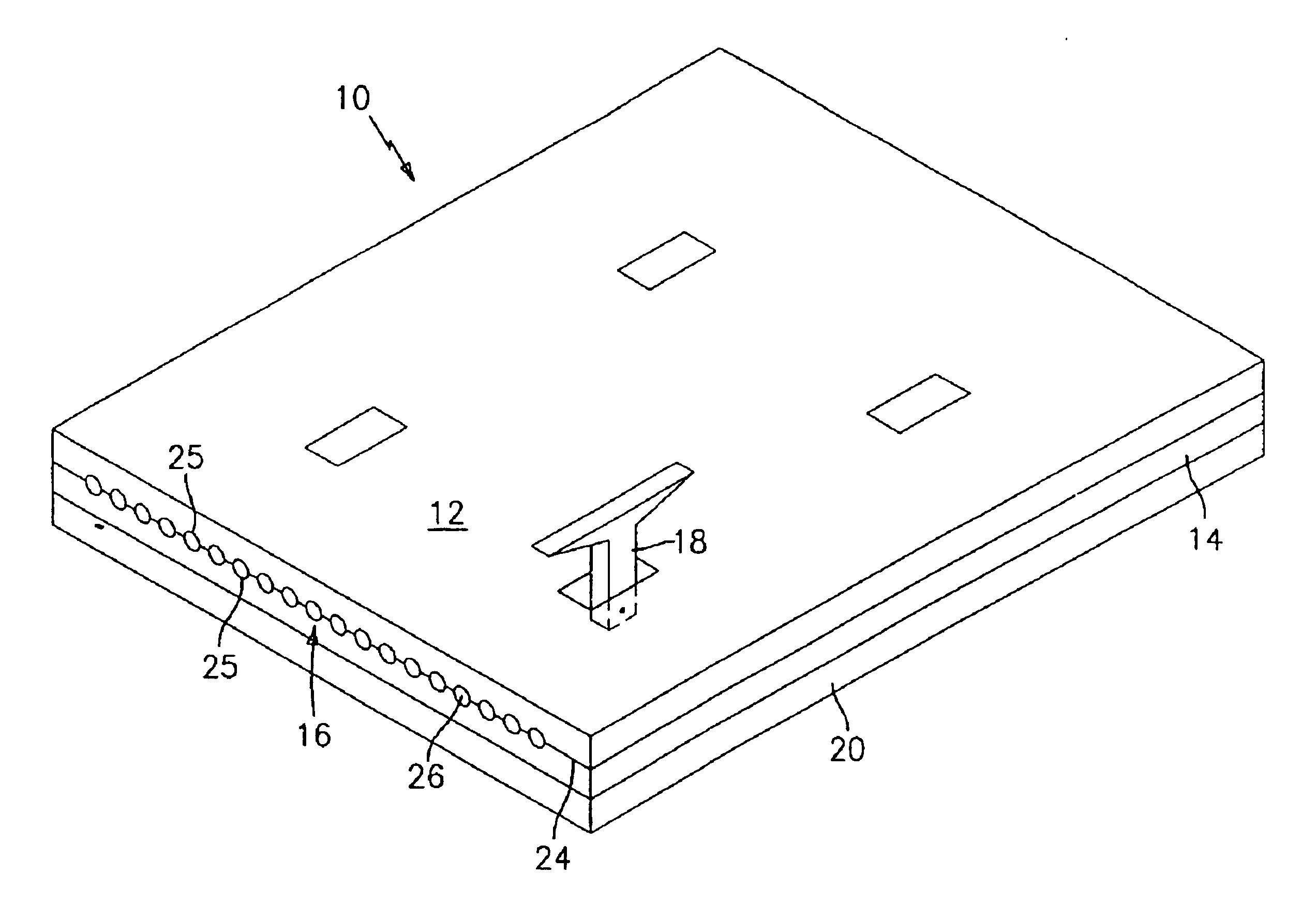
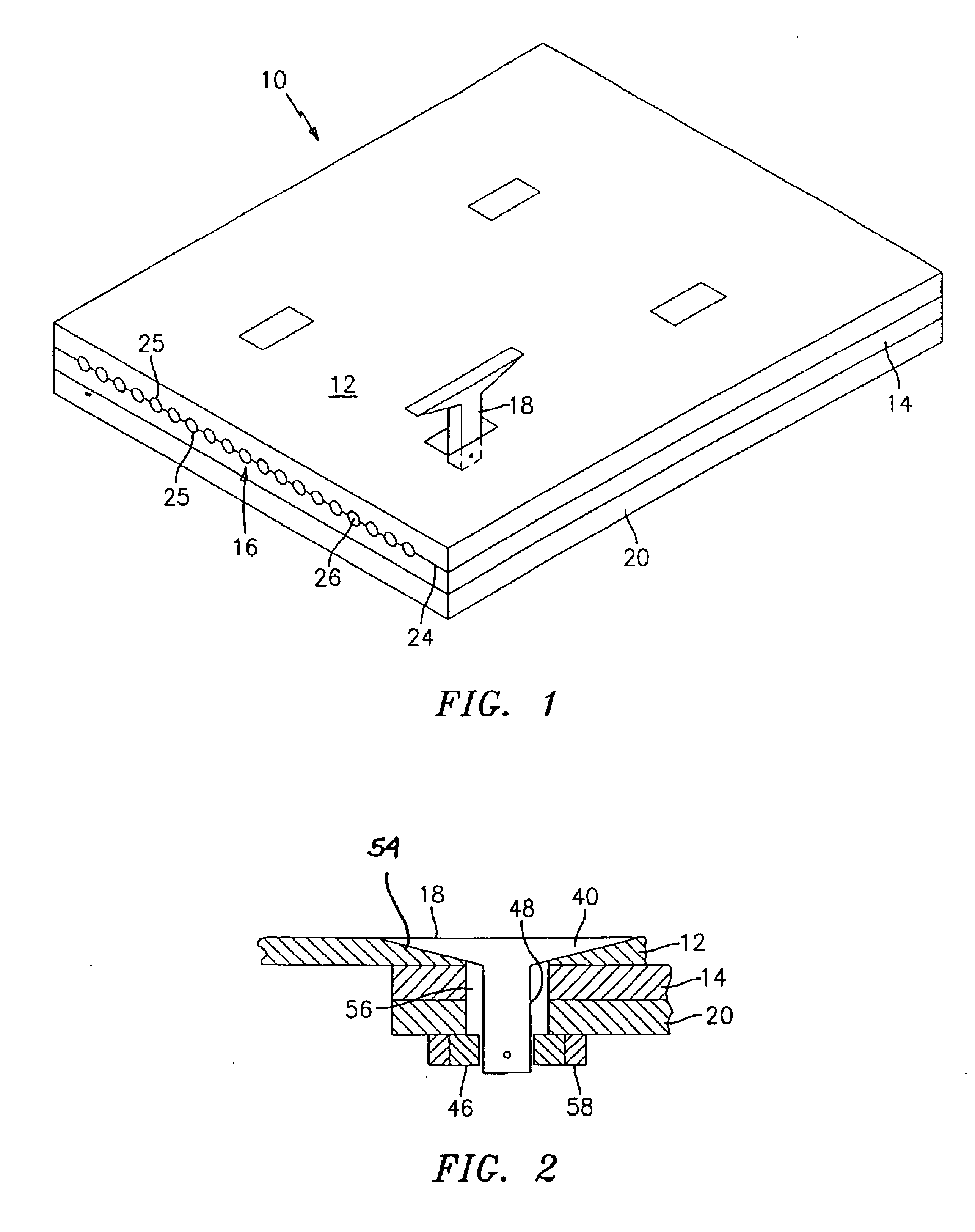
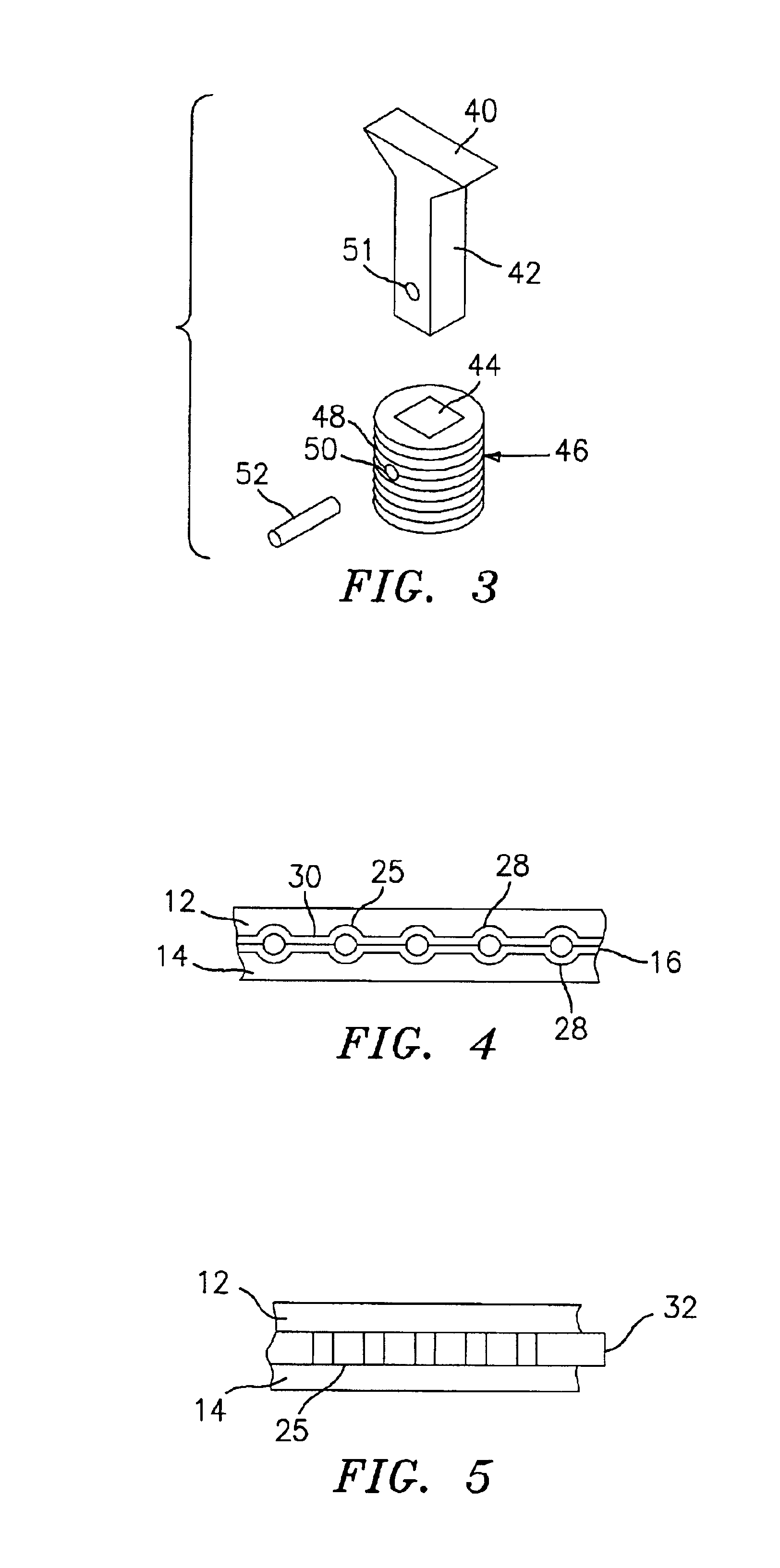
[0025]Referring now to the drawings, FIGS. 1 and 2 illustrate a heat exchanger panel 10 in accordance with the present invention. The heat exchanger panel 10 includes a first panel 12, a second panel 14, and a fluid containment device 16 positioned intermediate the first and second panels 12 and 14. The fluid containment device 16 may be formed from any suitable metallic and / or non-metallic materials known in the art, such as composite materials. In accordance with the present invention, the fluid containment device 16 is not fastened to either panel 12 or panel 14 in any manner. Rather, it is merely sandwiched between the panels 12 and 14.

[0026]The panel 10 further includes one or more fasteners 18 for joining the first and second panels 12 and 14 together and / or for joining the heat exchanger panel 10 to a substructure 20, such as a load carrying substructure. When the panels 12 and 14 are joined together in this manner, they hold the fluid containment device 16 in place.

[0027]In...


PUM


Abstract

The present invention relates to a heat exchanger panel which has broad utility in high temperature environments. The heat exchanger panel has a first panel, a second panel, and at least one fluid containment device positioned intermediate the first and second panels. At least one of the first panel and the second panel have at least one feature on an interior surface to accommodate the at least one fluid containment device. In a preferred embodiment, each of the first and second panels is formed from a high conductivity, high temperature composite material. Also, in a preferred embodiment, the first and second panels are joined together by one or more composite fasteners.

Description

STATEMENT OF GOVERNMENT INTEREST[0001]Government has rights in this invention, pursuant to Contract No. NAS3-00177 awarded by NASA.BACKGROUND OF THE INVENTION[0002]The present invention relates to a novel heat exchanger panel which has particular utility in high temperature environments, such as in air breathing and rocket propulsion systems.[0003]One method for fabricating a high temperature capability composite heat exchanger comprised processing or densifying a composite material with high temperature capability and metallic coolant containment tubes integrally assembled into the composite. This method required the use of expensive and high density (heavy) metal tubes which could not be removed for inspection or replacement. As a result, these old heat exchangers were heavy, costly, difficult to inspect, and virtually impossible to maintain.SUMMARY OF THE INVENTION[0004]Accordingly, it is an object of the present invention to provide a heat exchanger panel which is less complex, ...

Claims


Application Information

Patent Timeline
Patent Type & Authority Patents(United States)
IPC IPC(8): F28F21/04F28F3/12F28F3/00F23R3/00F28F21/00F28D1/03
CPCF23R3/007F28F21/04F28F3/12F28D2021/0078
Inventor WARBURTON, ROBERT E.CUVA, WILLIAM J.
Owner AEROJET ROCKETDYNE INC
Why Eureka
Try Eureka