
Optical security system

a security system and optical technology, applied in the field of multi-purpose optical systems, can solve the problems of lowering the security of a mechanical system, affecting the operation of the system,

Inactive Publication Date: 2005-06-21
EASTMAN KODAK CO
View PDF8 Cites 6 Cited by
  • Summary
  • Abstract
  • Description
  • Claims
  • Application Information

AI Technical Summary

Benefits of technology

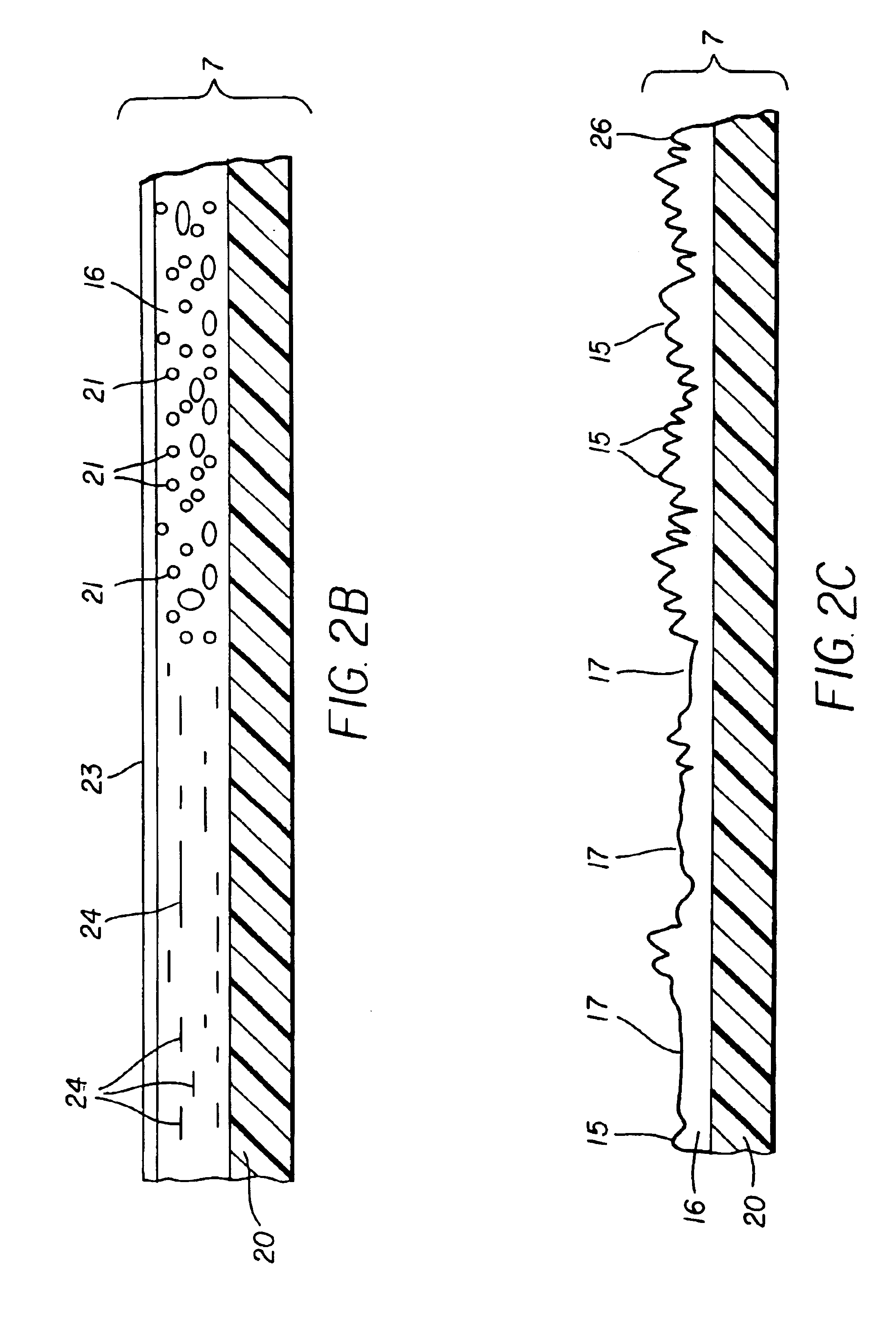
The present invention provides a security card with a unique pattern that can be read from the light passing through. The security card has a support substrate with a diffuse layer or a lens layer with a predetermined pattern area. The method for forming the unique pattern on the security card involves modifying the index of refraction of the diffuse layer in the unique pattern. The system for controlling access to a user includes a database for maintaining a plurality of unique security patterns each associated with a designated security card, a security card with the modified diffuse layer or lens layer, a reader for reading the security card, and a computer system for comparing the read information with the database to determine if the read associated unique pattern will be allowed access.

Problems solved by technology

However, people such as safebreakers can easily tamper with them.
The keys can be copied conveniently in stores and locks are labor-intensive to change, both of which lower the security of a mechanical system.
Magnetic systems can be problematic because of the degradation of the key (loss of magnetic force) in the presence of ferromagnetic objects or heat.
They are also not high in security due to the limited number of magnetic combinations and the ease in copying a magnetic key.
The system is advantageous due to the lack of a separate key and large number of possible combinations; however, the system loses security as the keypad wears and the system is costly to implement.

Method used


Image

  • Optical security system
  • Optical security system
  • Optical security system

Examples


Embodiment Construction

[0035]The invention has been described in detail with particular reference to certain preferred embodiments thereof, but it will be understood that variations and modifications can be effected within the spirit and scope of the invention. With reference to the drawings, a new and improved secure entry system will be described.

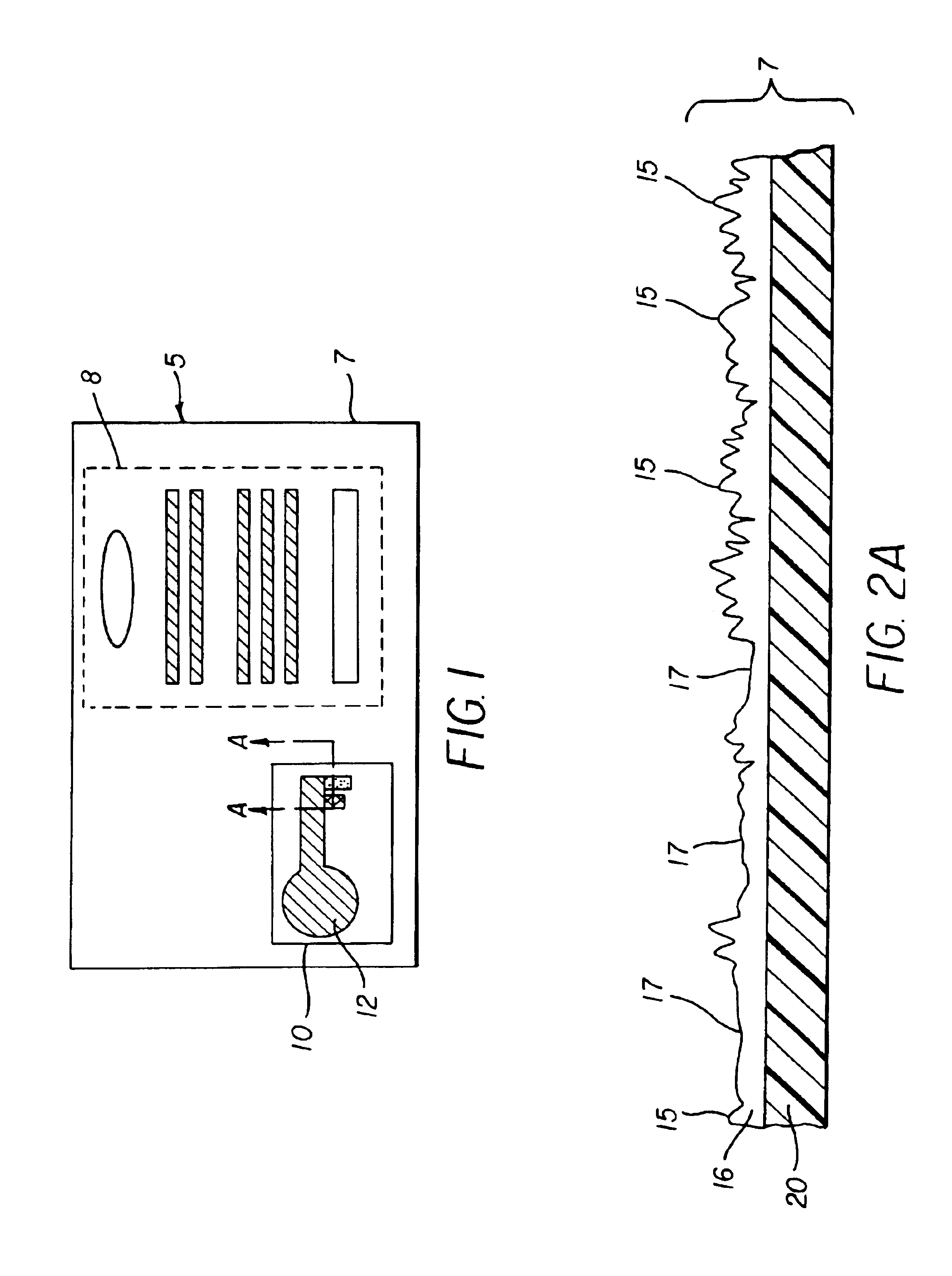
[0036]FIGS. 1 and 2A illustrate a key (5) comprised of a multi-layer material (7). The key (5) consists of a patterned area (10) a multi-layer material (7). The pattern area (10) contains a pattern (12). This patterned area (10) could extend to the perimeter of the key (5), or could be a portion thereof as illustrated. Outside of the patterned area (10), the key (5) might contain an area of printed information (8) specific to the key's purpose. If the key were to be used to gain entry into a hotel room, the printed information may include a logo and lettering of the hotel name and location, as well as phone number and room number information. If the key were to...


PUM


Abstract

A system and security card comprising a support substrate having a diffuse layer disposed thereon, the support substrate having a substantially uniform light transmitting characteristic, the lens layer having a predetermined pattern area formed thereon such that when light is transmitted through the support substrate and the diffuse layer a unique pattern is produced that can be read from the light passing there through.

Description

FIELD OF THE INVENTION[0001]The present invention relates to a multi-purpose optical system, comprising a security key made of polymers, or dyes, which can be coded on-demand, with a randomly generated pattern.BACKGROUND OF THE INVENTION[0002]There are several methods for producing security keys. These methods disclose mechanical, magnetic and micro-processor devices, which have all been used to secure an entry point.[0003]Mechanical locking systems, in which a key is used to turn a locking device between a locked state and an unlocked state, are very simple and inexpensive systems. However, people such as safebreakers can easily tamper with them. The keys can be copied conveniently in stores and locks are labor-intensive to change, both of which lower the security of a mechanical system.[0004]Magnetic systems involve the use of magnets both in the key and the locking mechanism. Locks are locked or unlocked by the turning of the magnetic pieces within the locking mechanism. Magnetic...

Claims


Application Information

Patent Timeline
Patent Type & Authority Patents(United States)
IPC IPC(8): E05B49/00G06K1/00G06K1/12G06K7/10G06K7/12G06K19/06
CPCE05B49/006G06K1/123G06K1/126G06K7/10732G06K7/1417G06K19/06037G06K19/06046G06K7/12G07C2209/41G06K2019/06271
Inventor BENCH, AMY L.PATTON, DAVID L.BOURDELAIS, ROBERT P.KAMINSKY, CHERYL J.SPOONHOWER, JOHN P.
Owner EASTMAN KODAK CO
Learn More