Unit injector with stabilized pilot injection

a technology of pilot injection and injector, which is applied in the direction of fuel injector, machine/engine, mechanical equipment, etc., can solve the problems of unstable pilot injection, unstable pilot injection, and undesirable pressure fluctuation (spikes)

Inactive Publication Date: 2005-06-21
CATERPILLAR INC
View PDF4 Cites 13 Cited by
  • Summary
  • Abstract
  • Description
  • Claims
  • Application Information

AI Technical Summary

Benefits of technology

[0004]In one aspect of the subject invention, a unit injector assembly is provided for controllably delivering fuel to a combustion chamber of an engine. The unit injector assembly includes an injector body having a plunger piston bore and an injection chamber bore defined therein. A valve assembly is disposed in the injector body and is selectively movable between a flow passing position and a flow blocking position. A plunger assembly is disposed in the injector body and has a plunger piston disposed in the plunger piston bore of the injector body to define a pumping chamber therein. An in...

Problems solved by technology

In many of these known systems, unstable pilot injection may occur.
These unstable pilot injections may be a result of fluctuations in the pressure in the system due to the fluid dynamics therein.
The pressure variations are typically a resu...

Method used


Image

  • Unit injector with stabilized pilot injection
  • Unit injector with stabilized pilot injection
  • Unit injector with stabilized pilot injection

Examples


Embodiment Construction

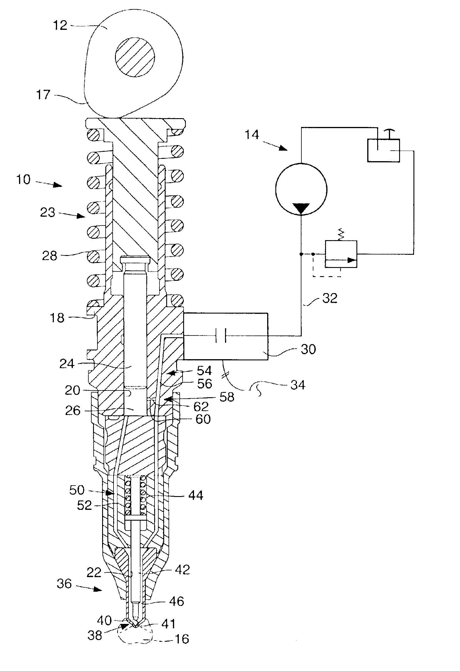
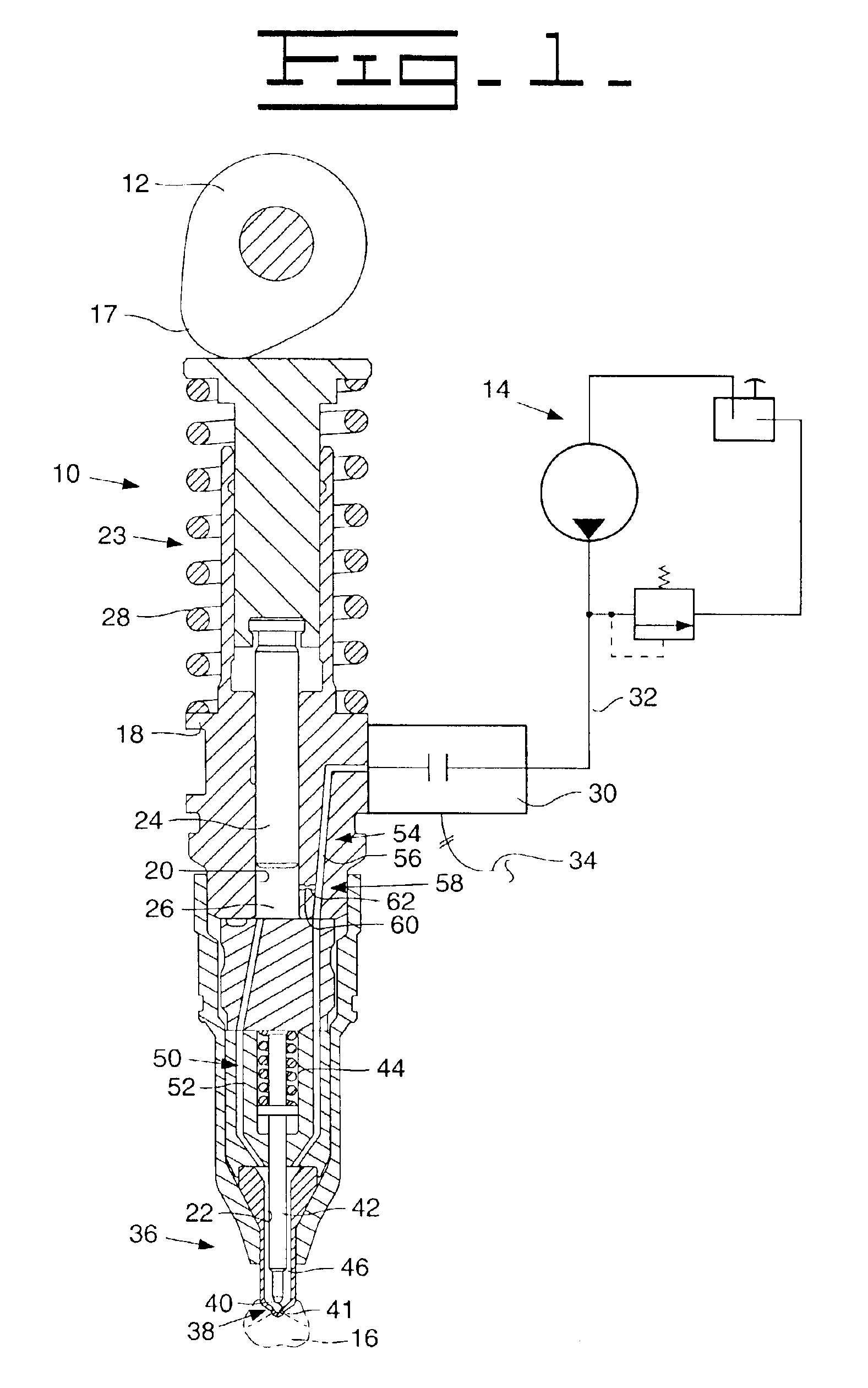
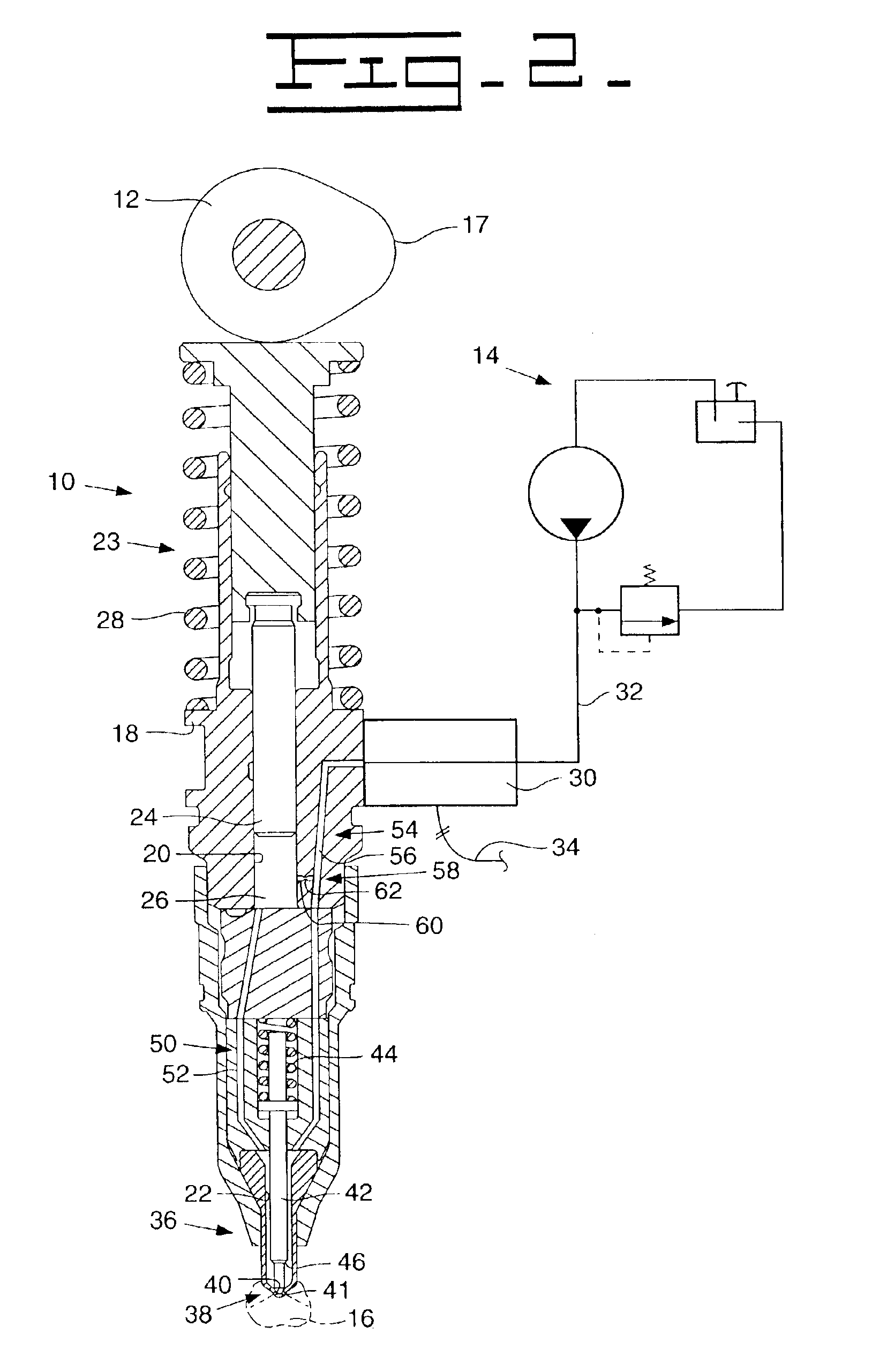
[0008]Referring to FIGS. 1 & 2, a unit injector assembly 10 is illustrated in cooperation with a cam arrangement 12 of an engine (not shown), a source of fuel 14, and a combustion chamber 16 of the engine (not shown). The cam arrangement 12, in a well known manner, has a cam lobe 17 disposed thereon.

[0009]The unit injector assembly 10 includes an injector body 18 having a plunger piston bore 20 and an injection chamber bore 22 defined therein. A plunger assembly 23 has a plunger piston 24 that is slideably disposed in the plunger piston bore 20 and defines a pumping chamber 26 in the plunger piston bore 20. The plunger piston 24 extends from the injector body 18 and is in mating contact with the cam arrangement 12. The plunger piston 24 is biased towards the cam arrangement by a spring 28. It is recognized that the plunger piston 24 could be composed of two or more elements without departing from the essence of the subject invention.

[0010]A valve assembly 30 is operatively disposed ...


PUM


Abstract

A unit injector assembly is provided that helps to ensure maximum injection flow while minimizing the harmful affects of pressure waves within the unit injector assembly. The unit injector assembly has a first fuel passageway extending from the plunger piston pumping chamber to the tip check stem injection chamber and valve seat. The unit injector assembly has a second fuel passageway extending from the tip check stem injection chamber to a fuel control valve assembly. A flow restricting fuel passageway connects one of the pumping chamber and the first fuel passageway with the second fuel passageway and acts to minimize cavitation at the valve seat and effectively eliminates pressure waves within the unit injector assembly.

Description

TECHNICAL FIELD[0001]This invention relates generally to a unit fuel injector for an internal combustion engine and more particularly to a unit injector having a stabilized pilot injection.BACKGROUND[0002]Unit fuel injectors are well known in the art for controlling the timing and volume of fuel being injected into respective combustion chambers of an engine. Typically, many of these unit injectors are mechanically or hydraulically actuated. In most applications currently used, the timing of the respective injections are controlled electronically based on various system parameters. In one example of these known unit injectors, fuel is delivered to a pumping chamber through an electrically controlled valve assembly and a plunger piston acts in response to rotation of a cam arrangement moving the plunger piston to force the fuel from the pumping chamber. When the electrically controlled valve assembly is closed, the fuel is forced towards a pressure responsive check valve and subseque...

Claims


Application Information

Patent Timeline
IPC IPC(8): F02M57/00F02M57/02F02M45/08F02M45/04F02M45/06F02M45/00
CPCF02M45/04F02M57/023F02M45/08F02M45/06
Inventor DONG, MINGCHUNSANDHU, AVTAR S.
Owner CATERPILLAR INC
Why Eureka
Try Eureka