Interlining panel structure for multiple socket

a technology for interlining panels and sockets, applied in the direction of coupling bases/cases, coupling device connections, electrical appliances, etc., can solve the problems of repeated occurrence of power cutoffs, unintended plug pulling, and difficulty in distinguishing which plug belongs to which electric applian

Inactive Publication Date: 2005-06-21
HUANG PEI CHIN
View PDF5 Cites 30 Cited by
  • Summary
  • Abstract
  • Description
  • Claims
  • Application Information

AI Technical Summary

Benefits of technology

[0009]The primary object of the invention is to provide a multiple socket having clear indicative functions, wherein each set of receptacles or switches is labeled for indicating corresponding electric appliances, thereby enabling a user to appropriately turn on and off power supplies of the electric appliances using the multiple socket.
[0010]The secondary object of the invention is to provide a multiple socket having readily replaceable decorative drawings or illustrative texts, thereby offering the multiple socket with an easily changed appearance for complying with manufacturing requirements of having diversified styles and small quantities.
[0011]The other object of the invention is to provide a multiple socket having special visual effects, wherein a three-dimensional interlining effect formed by a transparent plate thereof offers the multiple socket with an enhanced texture.

Problems solved by technology

Since a multiple socket has multiple sets of receptacles and even multiple sets of switches, it is rather difficult to distinguish which plug belongs to which electric appliance when all the receptacles are inserted with plugs.
Hence, pulling unintended plugs that further incurring accidental power cutoffs is considered as repeated occurrence.
However, this structure still has drawbacks when put to use due to the following reasons:1. This structure merely uses distinct colors as a measure for identification, but lacks a method for a user to remember electric appliances represented by individual colors.
Therefore, the measure using colors is not at all practical.2. According to this structure, identification is carried out through colors of the identification cards at the socket.
However, when a plug of an adaptor having a larger volume is inserted into this structure, the identification cards are likely to be concealed by the adaptor plug.
Consequently, a user cannot easily make appropriate identifications even in the presence of the identification cards having distinct colors.
Nevertheless, these sticker labels are prone to cock up or peel off owing to temperature change or slackening of adhesive properties thereof, and thus again offering inadequate practicability.
Suppose that the aforesaid texts, drawings and symbols are directly stamped or printed onto a surface of the multiple socket, although the texts, drawings and symbols are unlikely to fall off, production costs thereof are relatively much higher.
In addition, this method hardly fulfills requirements of small quantities and diversified styles.

Method used


Image

  • Interlining panel structure for multiple socket
  • Interlining panel structure for multiple socket
  • Interlining panel structure for multiple socket

Examples


first embodiment

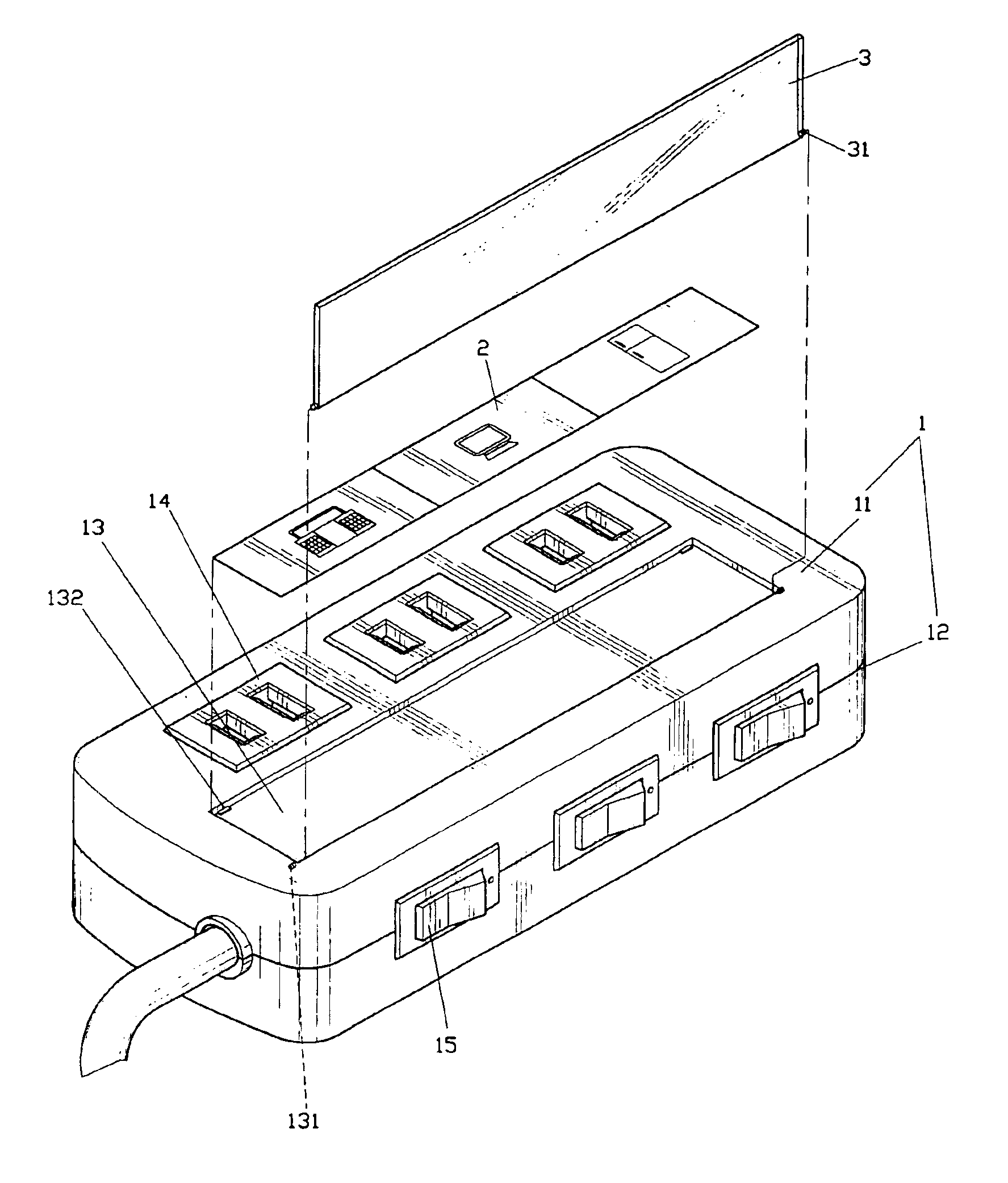
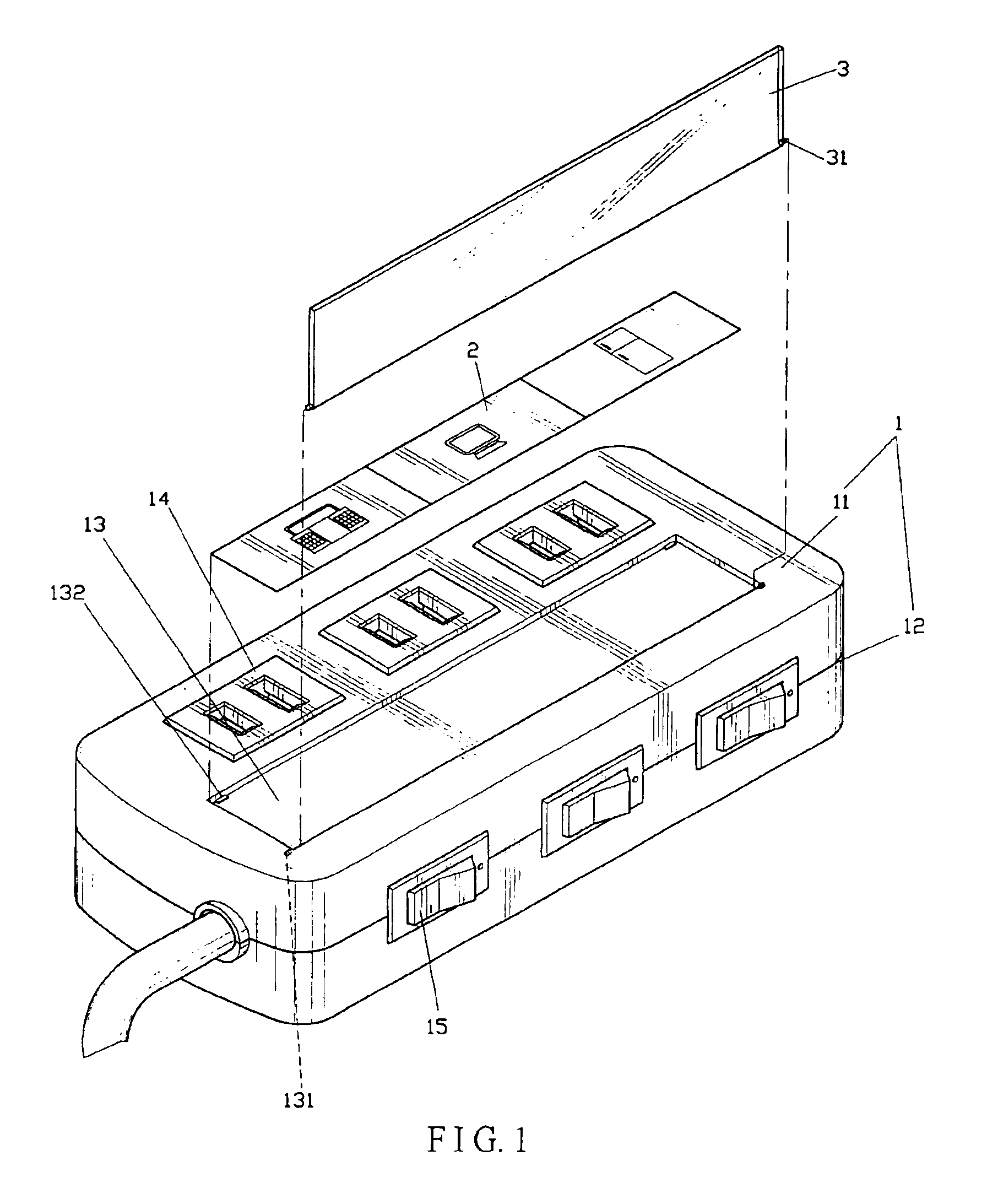
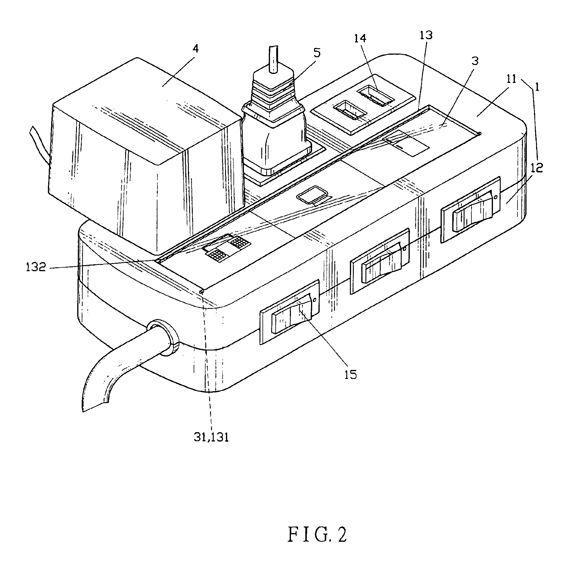
[0021]Referring to FIG. 1 showing a structure of a first embodiment, the invention comprises a housing 1, an indication object 2 and a transparent plate 3.

[0022]The housing 1 is consisted of a cover 11 and a base 12. The cover 11 is provided with a dented embedding region 13. The embedding region 13 is disposed with a pivotal opening 131 at two corners of one side thereof, respectively, and is formed with a projecting butting piece 132 at inner edges of the other side thereof, respectively. The housing 1 is further provided with corresponding receptacles 14 and switches 15.

[0023]The indication object 2 is provided according to a size of the embedding region 13, and is a thin slice made of an acrylic board, a piece of paper or a plastic board. The indication object 2 is further provided with drawings or texts corresponding to positions of the receptacles 14 and switches 15. In addition, the indication object 2 may also display drawings, brand name, illustrative texts or decorative gr...

second embodiment

[0026]Referring to FIG. 3 showing a second embodiment according to the invention, a housing 1A is provided with an embedding region 13A at a cover 11A and between the receptacles 14 and switches 15. The embedding region 13A is disposed with a wedge groove 131A at two corresponding inner edges thereof, respectively. Two sides of a transparent plate 3A are similarly formed with a wedge portion 31A for corresponding with the wedge grooves 131A, respectively. One end portion of the transparent plate 3A is additionally provided with a vertical baffle portion 32A. The wedge portions 31A of the transparent plate 3A are slid and wedged at the corresponding wedge grooves 131A, and an exit of the end portion is blocked by the baffle portion 32A for preventing accidental falling off of the indication object 2. The indication object 2 is then placed at the embedding region 13A for offering same indicative purposes.

third embodiment

[0027]Referring to FIG. 4 showing a third embodiment according to the invention, a cover 11B of a housing 1B is provided with an embedding region 13B having positioning holes 131B. A transparent plate 3B is a board, and has a lower side thereof disposed with positioning pillars 24B for corresponding with the positioning holes 131B at the embedding regions 13B. For assembly, the indication object 2 is placed within the embedding region 13B, and the positioning pillars 31B at the lower side of the transparent plate 3B are inserted into and positioned at the positioning holes 131B at the embedding region 13B.


PUM


Abstract

An interlining structure for a multiple socket includes a housing, an indication object and a transparent plate. The housing is consisted of a cover and a base, and the cover is provided with a plurality of receptacles or even switches. The housing is further disposed with a dented embedding region for the transparent plate to cover thereon. A covered range of the transparent plate is placed with the indication object containing contents that are viewable from an exterior of the transparent plate. The indication object has related drawings and texts for indicating uses of the receptacles or switches, or other decorative and illustrative drawings and texts.

Description

BACKGROUND OF THE INVENTION[0001](a) Field of the Invention[0002]The invention relates to an interlining panel structure for a multiple socket, and more particularly, to an interlining panel structure having a dented embedding region disposed at a housing of the multiple socket so as to provide a transparent plate to cover thereon, and an indication object placed at a covered range of the transparent plate. Contents of the indication object are viewable from an exterior of the transparent plate. The indication object has related drawings and texts indicating uses of receptacles or switches of the multiple socket, or other decorative and illustrative drawings and texts.[0003](b) Description of the Prior Art[0004]A multiple socket is formed by disposing a multiple sets of receptacles on a same housing, which then becomes a unit having multiple sets of receptacles. The unit is connected to a power supply via a relatively long power line in order to provide individual receptacles at the...

Claims


Application Information

Patent Timeline
Patent Type & Authority Patents(United States)
IPC IPC(8): H01R13/46H01R25/00H01R13/70
CPCH01R13/465H01R25/003H01R13/70
Inventor HUANG, PEI-CHIN
Owner HUANG PEI CHIN
Why Eureka
Try Eureka