Automatic threshold control device for burst mode optical receiver

a threshold control and burst mode technology, applied in the field of burst mode optical receivers, can solve the problems of complex receiver circuitry, difficult to accurately control the reset timing, and cost of replacing existing subscriber networks composed of copper wires, and achieve the effect of accurately and quickly restoring the received burst mode data

Inactive Publication Date: 2005-06-21
SAMSUNG ELECTRONICS CO LTD
View PDF7 Cites 19 Cited by
  • Summary
  • Abstract
  • Description
  • Claims
  • Application Information

AI Technical Summary

Benefits of technology

[0016]Another object of the present invention is to provide an automatic threshold control device for a giga-class burst mode optical receiver that is capable of receiving burst mode data that is different in amplitude and phase on a packet basis and restoring the received burst mode data accurately and rapidly.

Problems solved by technology

However, a significant shortcoming of the conventional FTTH systems is that it is very costly to replacing existing subscriber networks composed of copper wires.
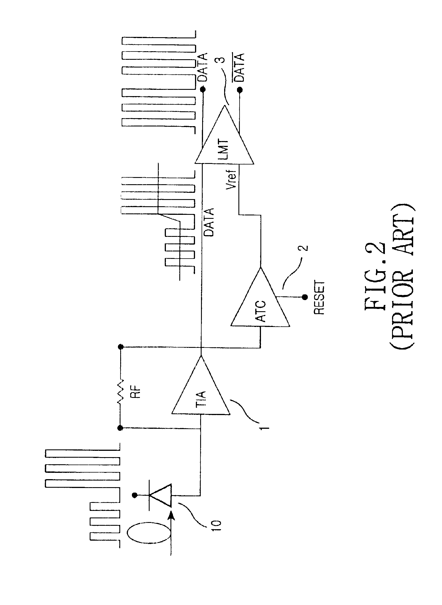
However, the above-mentioned conventional burst mode optical receiver has a disadvantage in that a reset signal for initialization in an inter-packet period is inputted through the use of an external additional circuit.
This makes it difficult to accurately control a reset timing.
In addition, the use of the external additional circuit makes the receiver circuitry complicated and increases the size of the receiver parts.

Method used


Image

  • Automatic threshold control device for burst mode optical receiver
  • Automatic threshold control device for burst mode optical receiver
  • Automatic threshold control device for burst mode optical receiver

Examples


Embodiment Construction

[0034]Now, preferred embodiments of the present invention will be described in detail with reference to the annexed drawings. In the drawings, the same or similar elements are denoted by the same reference numerals even though they are depicted in different drawings. In the following description of the present invention, a detailed description of known functions and configurations incorporated herein will be omitted when it may obscure the subject matter of the present invention.

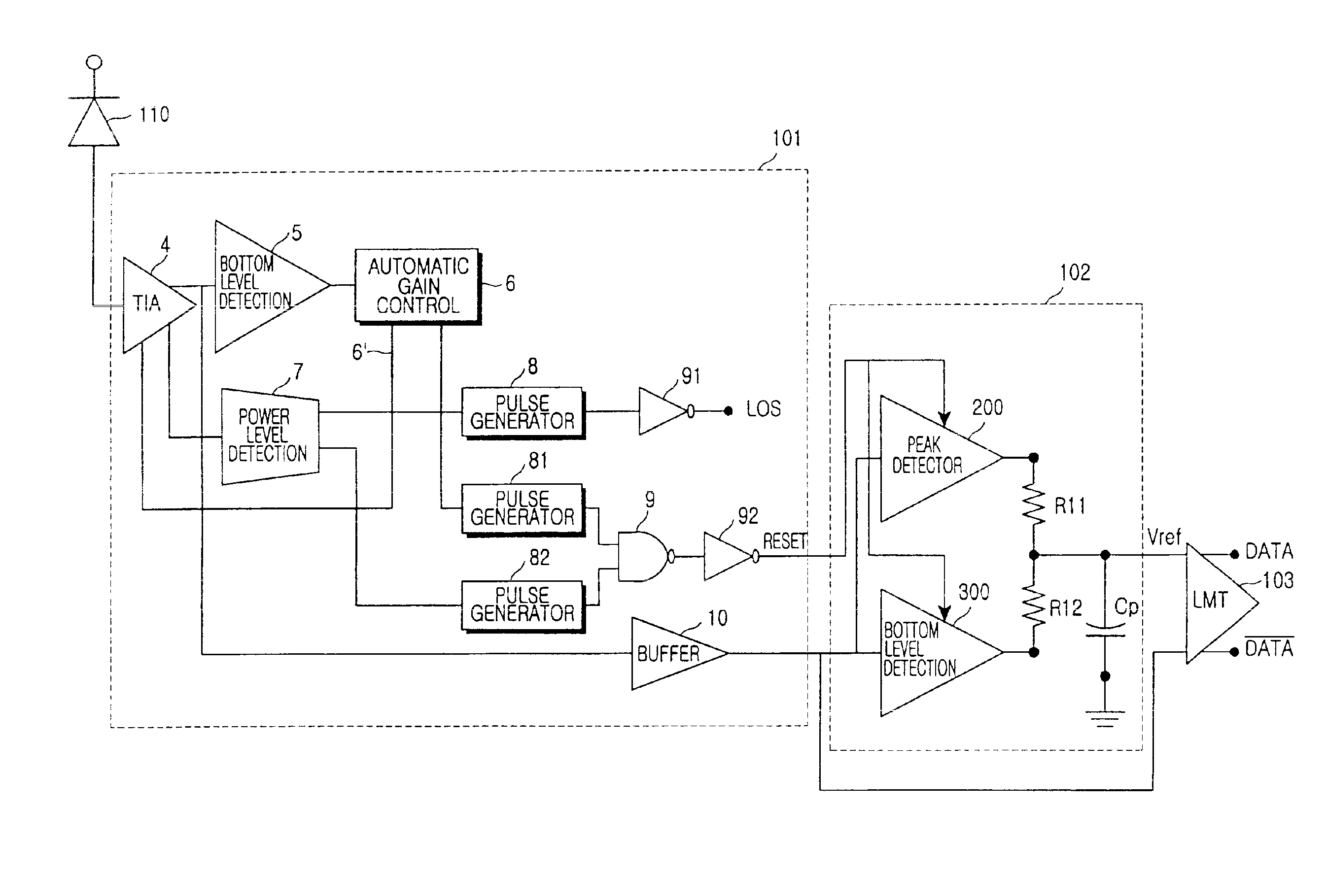
[0035]FIG. 3 schematically shows the construction of a burst mode optical receiver in accordance with aspects of the present invention. FIG. 4 is a more detailed diagram of the burst mode optical receiver shown in FIG. 3.

[0036]Referring to FIG. 3, the burst mode optical receiver includes an optical detector 110, a preamplifier 101, an ATC 102 and a limiting amplifier 103. It is noted that in one regard, the burst mode optical receiver shown in FIG. 3 is different from the conventional receiver shown of FIG. ...


PUM


Abstract

An automatic threshold control device for a burst mode optical receiver is disclosed. The receiver includes a converter that converts a burst mode signal into a voltage signal and an automatic gain controller for automatically controlling a gain of the converter, independently generating a reset signal and applying it to the automatic threshold control device. The automatic threshold control device is adapted to detect a voltage level of an output signal from the converter. The device includes a peak detector that detects a peak level of the output signal from the converter in response to the reset signal, a bottom level detector that detects a bottom level of the output signal from the converter in response to the reset signal, a pair of resistors having their one sides connected respectively to the peak detector and bottom level detector and their other sides connected to each other, the resistors generating a reference voltage on the basis of voltages of the peak level and bottom level, and a capacitor for storing the reference voltage.

Description

CLAIM OF PRIORITY[0001]This application claims priority to an application entitled “AUTOMATIC THRESHOLD CONTROL DEVICE FOR BURST MODE OPTICAL RECEIVER,” filed in the Korean Industrial Property Office on Apr. 25, 2002 and assigned Serial No. 2002-22714, the contents of which are hereby incorporated by reference.BACKGROUND OF THE INVENTION[0002]1. Field of the Invention[0003]The present invention relates to burst mode optical receivers, and more particularly to an automatic threshold control device for a burst mode optical receiver that is capable of determining whether an input signal is present and independently generating a reset signal for initialization in an inter-packet period in accordance with the determination.[0004]2. Description of the Related Art[0005]In order to more rapidly transfer a large amount of information to subscribers, next-generation communication techniques require an FTTH (fiber to the home) system. In such conventional FTTH systems, an optical line is insta...

Claims


Application Information

Patent Timeline
Patent Type & Authority Patents(United States)
IPC IPC(8): H04B10/152H04B10/158H04L25/06H04B10/07H04B10/272H03F3/45H04B10/40H04B10/50H04B10/516H04B10/524H04B10/564H04B10/58H04B10/60H04B10/61H04B10/69
CPCH04B10/6931H04L25/062H04B10/695H04B10/60
Inventor DOH, HEE-CHANKI, HYEON-CHEOLOH, YUN-JEPARK, GIL-YONGPARK, TAE-SUNGWON, SHIN-HEE
Owner SAMSUNG ELECTRONICS CO LTD
Why Eureka
Try Eureka