
Burst mode optical receiver

a technology of optical receiver and burst mode, which is applied in the direction of dc level restoring means or bias distort correction, baseband system details, gain control, etc., can solve the problems of high cost of replacing the existing subscriber network of copper wire, inability to accurately control the reset timing, and inability to amplitude constant incoming data packets

Inactive Publication Date: 2007-09-04
SAMSUNG ELECTRONICS CO LTD
View PDF8 Cites 3 Cited by
  • Summary
  • Abstract
  • Description
  • Claims
  • Application Information

AI Technical Summary

Benefits of technology

[0012]The present invention has overcomes the above problems and provides additional advantages, by providing a burst mode optical receiver that is capable of determining whether an input signal is present and independently generating an initial reset signal in accordance with the determined result.
[0013]One aspect of the present invention is to provide a giga-class burst mode optical receiver capable of receiving burst mode data that is different in amplitude and phase on a packet basis and restoring the received burst mode data accurately and rapidly.
[0014]Another aspect is that the present invention may be realized in a simple, reliable, and inexpensive implementation.
[0017]Preferably, the automatic gain controller may generate a control signal at the moment when the output signal from the converter begins to be distorted, so as to prevent the output signal from the converter from becoming too low due to a low operating reference level of the controller, or to prevent the controller from being operated after the output signal from the converter is distorted due to a high operating reference level of the controller.

Problems solved by technology

However, the FTTH system has drawbacks in that a high cost is involved in replacing the existing subscriber networks of copper wires.
Further, the incoming data packets are not constant in amplitude due to differences in the paths to the respective subscribers.
However, the conventional burst mode optical receiver has a disadvantage in that a reset signal for initialization in an inter-packet period is inputted via an external additional circuit, which in turn making it difficult to control the reset timing accurately.
Moreover, the use of the external additional circuit makes the receiver circuitry complicated and increases the size of the receiver components.

Method used


Image

  • Burst mode optical receiver
  • Burst mode optical receiver
  • Burst mode optical receiver

Examples


Embodiment Construction

[0026]Now, preferred embodiments of the present invention will be described in detail with reference to the annexed drawings. In the drawings, the same or similar elements are denoted by the same reference numerals even though they are depicted in different drawings. For the purposes of clarity and simplicity, a detailed description of known functions and configurations incorporated herein will be omitted as it may make the subject matter of the present invention unclear.

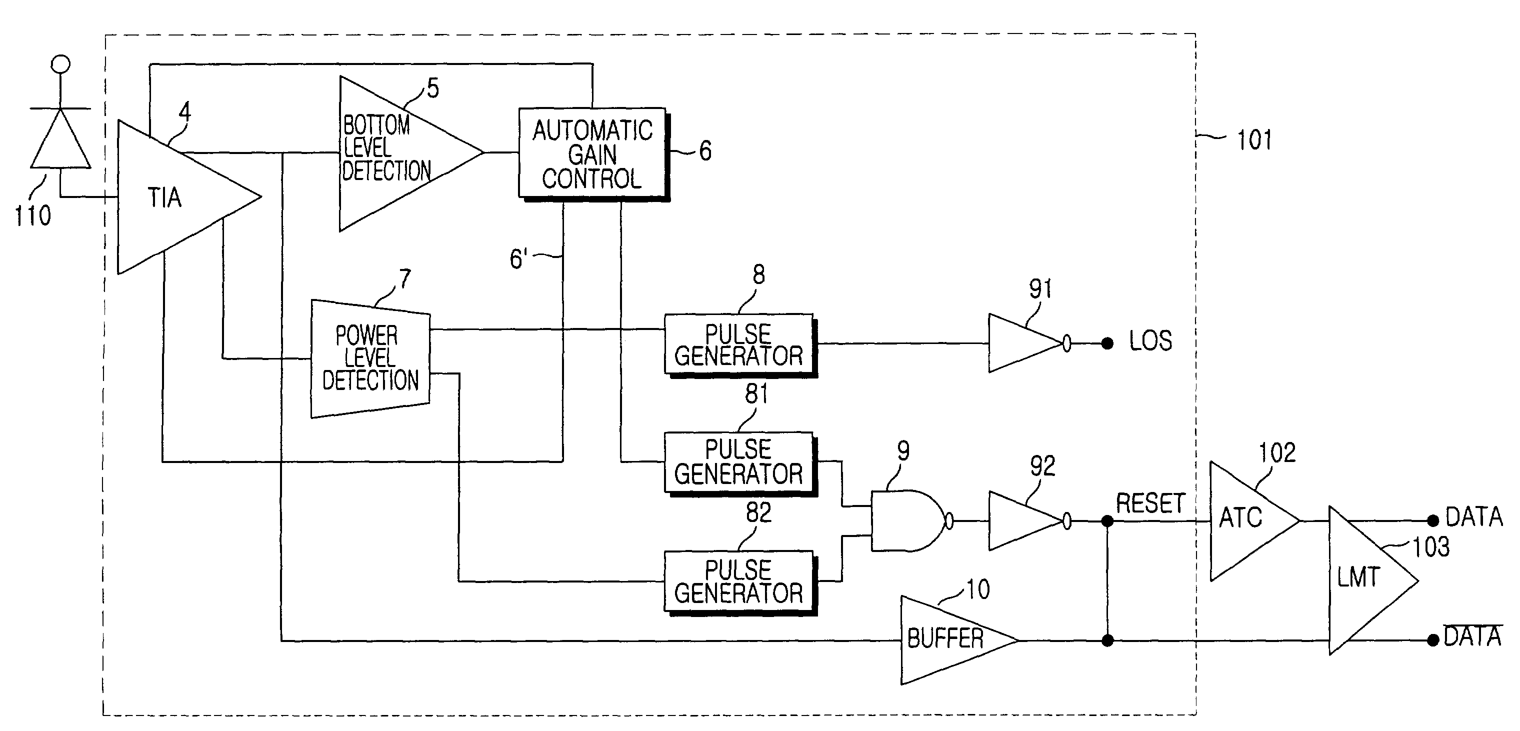
[0027]FIG. 3 shows the construction of a burst mode optical receiver in accordance with the embodiment of the present invention. As shown, the burst mode optical receiver includes an optical detector 110, a preamplifier 101, an automatic threshold controller (ATC) 102, and a limiting amplifier 103.

[0028]The preamplifier 101 includes a trans-impedance amplifier (TIA) 4 for determining the gain and bandwidth of the preamplifier 101, a bottom level detector 5 for detecting a bottom level of an output signal from the TI...


PUM


Abstract

A burst mode optical receiver is disclosed and includes a converter for converting a burst mode signal into a voltage signal, a bottom level detector for detecting a bottom level of an output signal from the converter, an automatic gain controller for automatically controlling the gain of the converter on the basis of the bottom level detected by the bottom level detector in order to maintain an amplitude of the output signal from the converter and generating a reset signal when the bottom level is lower than a predetermined reference value, and a power level detector for detecting a power level of the output signal from the converter and generating the reset signal and an LOS signal indicative of the presence of no input signal when the detected power level is lower than a predetermined reference value.

Description

CLAIM OF PRIORITY[0001]This application claims priority to an application entitled “BURST MODE OPTICAL RECEIVER”, filed in the Korean Industrial Property Office on Apr. 16, 2002 and assigned Serial No. 2002-20607, the contents of which are hereby incorporated by reference.BACKGROUND OF THE INVENTION[0002]1. Field of the Invention[0003]The present invention relates to burst mode optical receivers, and more particularly to a burst mode optical receiver for determining whether an input signal is present and independently generating a reset signal for the initialization of an inter-packet period in accordance with the determined result.[0004]2. Description of the Related Art[0005]In order to transfer a large amount of information more rapidly to subscribers, a next-generation communication system known as an FTTH (fiber to the home) system, which includes an optical line installed up to each home, has been introduced. However, the FTTH system has drawbacks in that a high cost is involve...

Claims


Application Information

Patent Timeline
IPC IPC(8): H04B10/06H04B10/40H03G3/30H04B10/07H04B10/272H04B10/50H04B10/516H04B10/524H04B10/54H04B10/58H04B10/60H04B10/61H04B10/69H04J14/08H04L25/06
CPCH03G3/3084H04B10/695H04L25/062H04B10/60H04B10/69
Inventor DOH, HEE-CHANPARK, GIL-YONGWON, SHIN-HEEKANG, BYUNG-CHANGPARK, TAE-SUNGKI, HYEON-CHEOL
Owner SAMSUNG ELECTRONICS CO LTD
Learn More