Device and method for displaying pictograms in a vehicle

a vehicle and display device technology, applied in the direction of cathode-ray tube indicators, identification means, instruments, etc., can solve the problems of reducing the size, reducing the size, and reducing the active display area of the display uni

Inactive Publication Date: 2005-06-21
CONTINENTAL AUTOMOTIVE GMBH
View PDF8 Cites 28 Cited by
  • Summary
  • Abstract
  • Description
  • Claims
  • Application Information

AI Technical Summary

Benefits of technology

[0008]The object of the present invention is to provide a device and a method for displaying pictograms in a vehicle, the device being composed of a control unit and a display unit, in particular an LC display unit, and the control unit controlling the display unit in which device a plurality of simultaneously present messages about the operational status of various devices in the vehicle are also displayed in an easily perceptible fashion in the form of pictograms.

Problems solved by technology

Moreover, the driver has to be made aware, quickly and in an easily comprehensible way, of faults in devices in the vehicle and of warnings of hazards.
However, it is also the case with these information modules that for technical and economic reasons the available active display area of the display unit cannot be increased as desired in order to display the increasing amount of simultaneously occurring messages.
For ergonomic reasons and for reasons of safety it is also not sensible to display a large number of messages simultaneously because the driver can only ever absorb a specific amount of information simultaneously and an excessively large quantity of information could also distract him from his actual task of driving.
Neither is it possible to reduce the size of the pictograms in order to be able to display simultaneously more pictograms on the available active display area of the display unit because this also infringes legal regulations for maintaining good legibility and clear recognizability.

Method used


Image

  • Device and method for displaying pictograms in a vehicle
  • Device and method for displaying pictograms in a vehicle
  • Device and method for displaying pictograms in a vehicle

Examples


Embodiment Construction

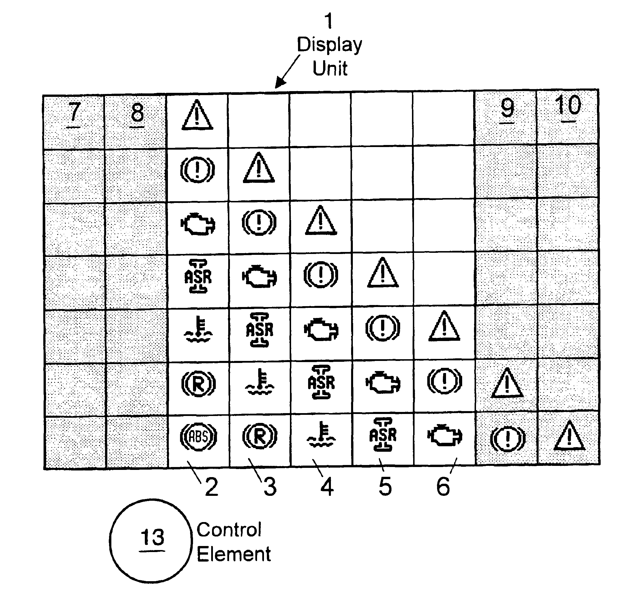
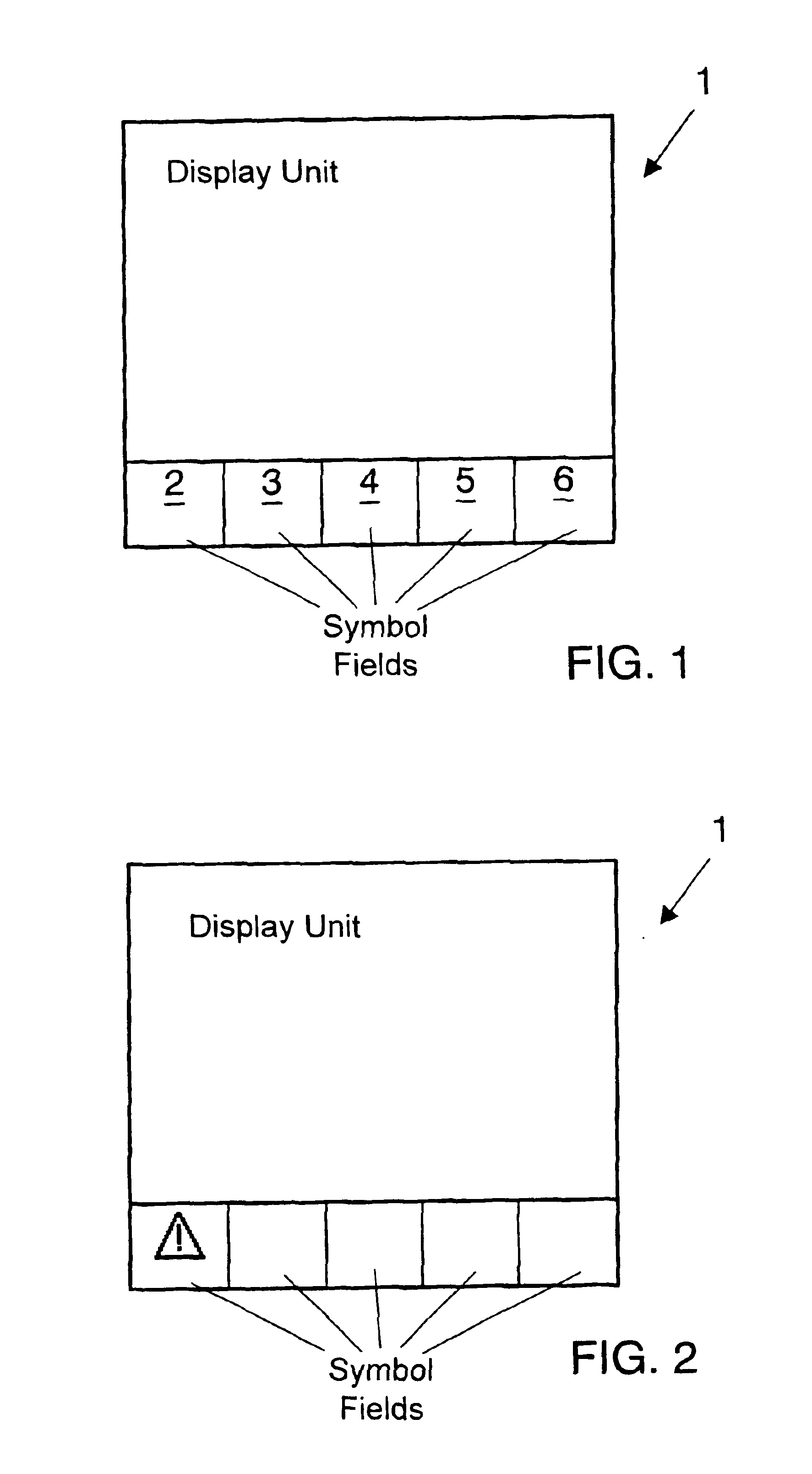
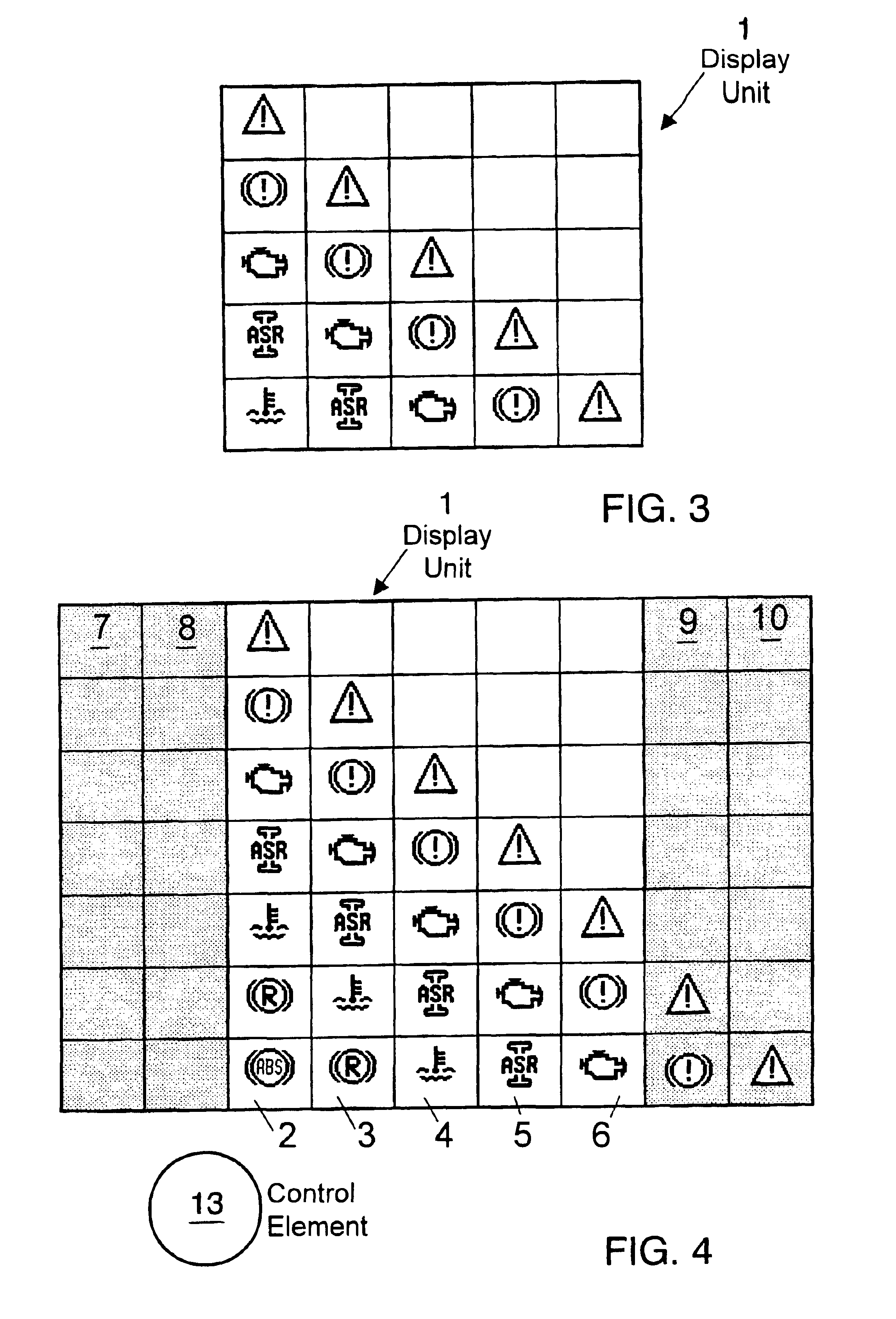
[0015]FIG. 1 shows a display unit 1 in the lower part of whose active display area a row of, for example, five symbol fields 2, 3, 4, 5, 6 is arranged. Depending on the actual design—in particular the size of the active display area—of the display unit selected in the implementation, the number of symbol fields may be larger or smaller than in this example. The upper part of the active display area should be reserved for purposes other than the display of pictograms. Here, it would be possible, for example, to display messages from a navigation system or texts.

[0016]If measuring control or instrumentation equipment of the vehicle outputs a message which informs the viewer of the display unit, i.e. as a rule the driver of the vehicle, of, for example, an operational status, makes him aware of a fault or warns him of a hazard, a pictogram which is assigned to this message is displayed in accordance with FIG. 2 in that the control unit which controls the display unit displays the corre...


PUM


Abstract

A device for displaying pictograms in a vehicle wherein the device comprises a control unit and a display unit, in particular an LCD display unit, the control unit controlling the display unit, and a method for operating the device, wherein
  • a) the display unit is divided into symbol fields (2, 3, 4, 5, 6) which are arranged one next to the other in a row, the control unit only ever displaying one pictogram in each symbol field simultaneously,
  • b) the control unit always displays in a specific symbol field (2) each new pictogram which is to be displayed in the symbol fields (2, 3, 4, 5, 6) which are arranged one next to the other in a row, and displaces by one symbol field the pictograms which have already been displayed, without changing their order,
  • c) a control element (13) is provided with which a coherent section of the pictograms which are arranged one next to the other in a row can be displayed in the symbol fields of the display unit if more pictograms are to be displayed simultaneously than symbol fields which are present on the display unit.
The method includes proposals for operating this device.

Description

FIELD AND BACKGROUND OF THE INVENTION[0004]The invention relates to a device for displaying pictograms in a vehicle comprising a control unit and a display unit, in particular an LC display, the control unit controlling the display unit.[0005]The dashboards of, in particular, utility vehicles and buses are equipped with a plurality of symbol lights in order to provide the driver with various information. Since the equipment in modern vehicles increasingly includes electronic control and instrumentation equipment and consequently the driver has to be made aware of more and more information, attempts are being made to find devices which can display the increasing amount of information in a manner which is easily manageable and can be satisfactorily perceived by the driver. Thus, recently, central information modules have become known which comprise an LC display which is arranged in the dashboard in the direct field of vision of the driver and on which information is displayed accordi...

Claims


Application Information

Patent Timeline
Patent Type & Authority Patents(United States)
IPC IPC(8): B60K35/00G09F9/35G09G5/34G06F3/048G06F3/0481G06F3/0487G09F9/00
CPCB60K35/00G09F9/35G09G5/343
Inventor SCHRADI, STEFANLEMKE, RAINERADAMS, JURGENKLOSTERMEIER, MICHAELSPADERNA, JOSEF
Owner CONTINENTAL AUTOMOTIVE GMBH
Why Eureka
Try Eureka