Operating device with electronics, at least partially operating as a dynamic balancer

a technology of dynamic balancer and operating device, which is applied in the direction of electrical locking circuits, mechanical apparatus, door/window fittings, etc., can solve the problem of high overall weight of the handle, and achieve the effect of reducing the weight of the handl

Active Publication Date: 2016-06-14
HUF HULSBECK & FURST GMBH & CO KG
View PDF5 Cites 0 Cited by
  • Summary
  • Abstract
  • Description
  • Claims
  • Application Information

AI Technical Summary

Benefits of technology

[0005]The invention provides an operating device for a locking device of a motor vehicle, in which the above-stated disadvantages are avoided, particularly in which an operating device is provided in which the weight of the dynamic balancer can be reduced and simultaneously it can be reliably ensured that in case of an accident the handle remains unmoved in its position at the door and thus any unintended opening of the door is prevented.
[0007]According to the invention, only the sensor element is left inside the handle, with the remaining electronics being displaced into the area of the motor vehicle, located at the inside of the door. This means that the weight and / or the mass of the handle can be considerably reduced by the displacement of the remaining electronics into the door. Consequently the mass of the dynamic balancer can be reduced, in order to effectively keep the handle immobile in the door in case of an accident when accelerations act upon the motor vehicle, without here any risk arising that the door opens. According to the invention the sensor element may be embodied such that it is embodied as a capacitive sensor or as a Piezo sensor. This means that the electronics recognize an approach to the handle via the capacitive sensor or sense a contact of the handle by the Piezo sensor. Advantageously, the electronics with their sensor element and their remaining electronics are a part of the security system, particularly an access and / or driving authorization control system. For example, the security system may represent a keyless system, keyless-go system, in which the vehicular electronics communicate with the ID-generator carried by the user. It has been shown advantageously that the sensor element arranged in the handle is insensitive with regard to environmental influences, such as soiling, moisture, etc., so that it is not mandatory to provide the handle with a molding mass in order to effectively protect the electronics from environmental influences, as common in prior art. This way, the handle can be embodied free from molding mass, so that the mass of the handle can be further reduced. Particularly, the material of the molding mass contributes to the overall weight of the handle being high. Due to the embodiment of the handle according to the invention without any molding mass, it is contributed that the mass of the dynamic balancer can also be considerably reduced. Consequently, a compact, well operating handle can be provided, which requires only low weight in reference to the dynamic balancer.
[0010]Advantageously, the remaining electronics may be integrated in the additional mass. This means that the additional mass, together with the remaining electronics, forms a uniform and / or joint component, which for example can be arranged at the coupling element. This additional mass may be embodied metallic, where particularly the additional mass may comprise a fastening element in order to reliably fasten the remaining electronics at the additional mass. Additionally, it is possible for the additional mass to comprise a cavity in which the remaining electronics are located. Advantageously, the cavity can be closed by a cover element in order to reliably protect the remaining electronics from environmental influences.
[0011]In another improved measure according to the invention, the handle may show a hollow chamber, by which the mass of the exterior handle can be considerably reduced. Advantageously, the handle is made from a plastic material. This weight reduction or mass reduction of the handle shows the positive consequence that here the mass of the dynamic balancer can also be considerably reduced.
[0015]Furthermore, it may be provided that the coupling element and / or the transmission element comprise a fastening means, at which the dynamic balancer, particularly the additional mass and / or the remaining electronics are fastened. Here, it is possible that the dynamic balancer can be fastened via a clip connection and / or a snap connection at the coupling element and / or the transmission element in an easily assembled fashion. Additionally, the fastening means may be embodied as an accept, in which the dynamic balancer can be fastened, particularly the additional mass and / or the remaining electronics, in a form- and / or force-fitting fashion and / or a material-to-material manner.
[0016]In a potential embodiment of the invention, a container may be provided in which the remaining electronics and / or the additional mass is / are arranged, with particularly the remaining electronics being sealed by a molding mass. The container therefore reliably accepts the remaining electronics and / or the additional mass. Here, the container may be fastened at the fastening means of the coupling element and / or the transmission element. The container itself may be embodied from an appropriate mass, so that the container forms the additional mass and simultaneously creates a cavity for the remaining electronics. The container may be closed via a cover element. Additionally, it is possible for the container to be fastened detachably at the coupling element and / or the transmission element. This way it is possible that the remaining electronics and / or the additional mass may be interchangeable depending on the application. In order to increase the seal of the remaining electronics inside the container, a molding mass may be inserted into the container, surrounding the remaining electronics. This ensures a reliable protection of the remaining electronics from environmental influences. The molding mass serves as an additional mass for the dynamic balancer.

Problems solved by technology

Particularly, the material of the molding mass contributes to the overall weight of the handle being high.

Method used


Image

  • Operating device with electronics, at least partially operating as a dynamic balancer
  • Operating device with electronics, at least partially operating as a dynamic balancer
  • Operating device with electronics, at least partially operating as a dynamic balancer

Examples


Embodiment Construction

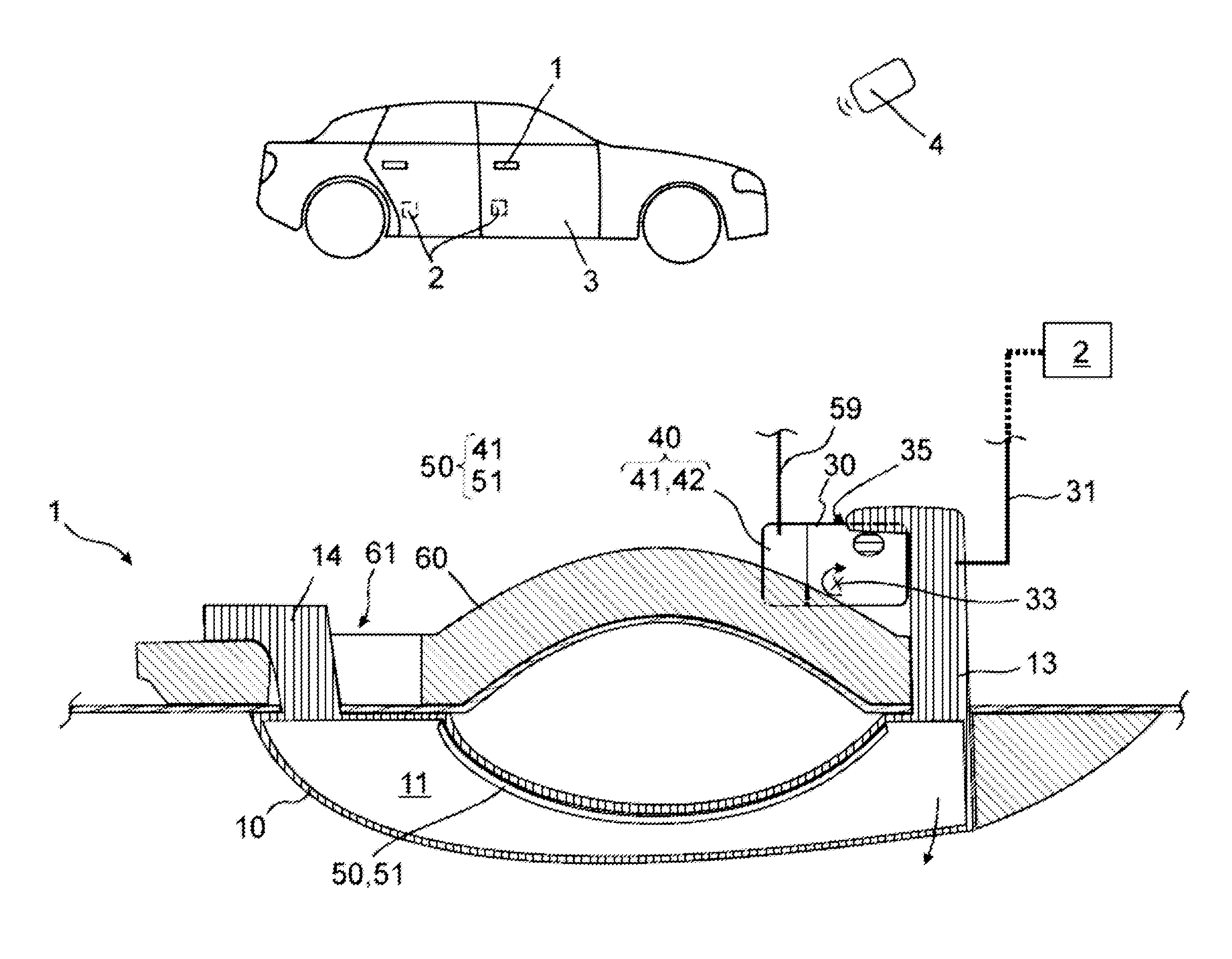
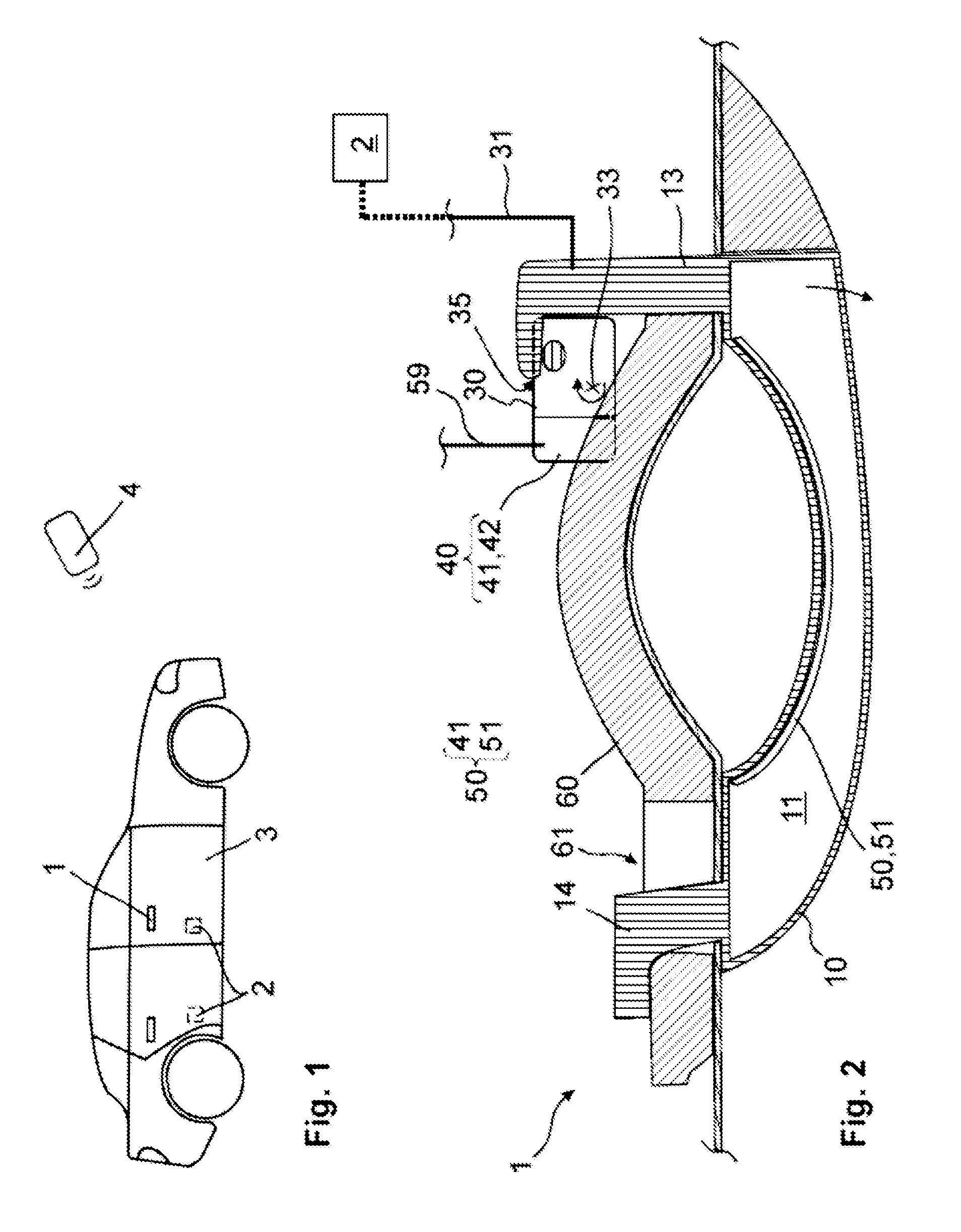
[0028]FIG. 1 schematically shows a motor vehicle, comprising at its door 3 an operating device 1 to be operated by the user from the outside. The operating device 1 is a component of a security system, particularly an access control system and / or a driving authorization control system. As schematically shown in FIG. 1, the door 3 comprises a lock 2, which can be addressed via a defined activation at the operating device 1. Depending on the respective application, a locking and / or unlocking can be triggered by the lock 2 via an approach and / or contact of the operating device 1. It is also possible that via an appropriate active pulling at the operating device 1 the lock 2 can be activated and moved such that an opening process of the door 3 can be realized and the user of the motor vehicle can enter it.

[0029]FIG. 2 shows a potential example of an operating device 1, which can be used in FIG. 1. As already mentioned, the operating device 1 is a component of a security system, particul...


PUM


Abstract

An operating device for a locking device of a motor vehicle, including a movable handle on a door of the motor vehicle, a dynamic balancer that prevents the accelerations acting on the motor vehicle as a consequence of an accident from causing the handle to move out of the door, electronics that respond to the approach of a user and, in case of engagement, trigger a defined function of the locking device, where the electronics comprise a sensor element, integrated in the handle, and remaining electronics, which can be fastened at the inside of the door, with the remaining electronics acting at least partially as a the dynamic balancer.

Description

TECHNICAL FIELD[0001]The invention relates to an operating device for a locking device of a motor vehicle, comprising a movable handle on a door of the motor vehicle, a dynamic balancer that prevents the accelerations acting on the motor vehicle as a consequence of an accident from causing the handle to move out of the door, and electronics that respond to the approach of a user and, in case of engagement, trigger a defined function of the locking device.BRIEF DESCRIPTION OF RELATED ART[0002]DE 20 23 859 C3 discloses an operating device, which cooperates with a locking device of a motor vehicle. Here, the operating device comprises a movable handle, which can be operated by the user at the exterior of the motor vehicle door. At the interior, a dynamic balancer is provided, which is arranged at the inside of the motor vehicle door.[0003]This dynamic balancer comprises a defined mass, which is additionally spring-loaded. In case of an accident, the dynamic balancer prevents the handle...

Claims


Application Information

Patent Timeline
Patent Type & Authority Patents(United States)
IPC IPC(8): E05B3/00E05B77/06E05B81/78E05B65/10E05B77/54
CPCE05B77/06E05B81/77E05B81/78E05B65/108Y10T292/57
Inventor MULLER, ULRICHSCHINDLER, MIRKO
Owner HUF HULSBECK & FURST GMBH & CO KG
Why Eureka
Try Eureka