Valve for metering a fluid

a valve and fluid technology, applied in the direction of valve housings, machines/engines, mechanical equipment, etc., can solve the problems of increasing production costs, micro-gaps between extrusion coatings and valve housings, and limited rotation of injection coatings relative to valve housings, so as to improve realization and function.

Active Publication Date: 2021-12-21
ROBERT BOSCH GMBH
View PDF25 Cites 0 Cited by
  • Summary
  • Abstract
  • Description
  • Claims
  • Application Information

AI Technical Summary

Benefits of technology

[0004]The valve according to the present invention may have the advantage that an improved realization and functioning are enabled. Moreover, a desired installation position of the valve in a receptacle bore of a cylinder head or the like and a rotational securing during operation can be realized in an improved manner.
[0007]A precondition for this is however that a positive-fit connection is ensured between the valve housing and the extrusion coating. If the valve housing is made up, at least in the area of the extrusion coating, only of rotationally symmetrical housing parts, such as rotated tubes, then the problem results that during operation, in particular after some changes of temperature, a micro-gap arises between the extrusion coating and the valve housing. During installation, or during operation, such a micro-gap can for example cause a possibly limited rotation of the injection coating relative to the valve housing. A possible flattening of housing parts on their outer side has the disadvantage of increasing the production costs. Another possible measure, which uses an additional part such as a clamping disc, also results in higher production costs.
[0008]A possible advantage of a rotational fixing is an improved exhaust gas composition. For example, through a defined distribution of fuel in the combustion chamber, a wetting of surfaces is avoided, reducing the development of soot. This is particularly relevant for the reduction of a cylinder capacity, because here the injection pattern of the valve has to be adapted as well as possible to the respective engine geometry and the flow conditions in the combustion chamber.
[0009]An embodiment according to the present invention may have the advantage that the receptacle can be easily fashioned on the external side of the housing part. A bore or a hole can be made in the housing part, for example using a laser. Preferably, one or more holes are bored by laser in the context of laser welding during the joining of housing parts of the valve housing. In a modified embodiment, it is also possible for one or more receptacles to form a structure on the outer side of the housing part. Such a structure can also be burned into the outer side of the housing part using a laser. This can also take place in the context of a joining of housing parts of the valve housing. However, it is also possible for the receptacles to be made on the outer side of the housing part at a different time, in particular before the assembly of the valve housing. If a plurality of receptacles are fashioned on the outer side, in accordance with one example embodiment, then these can be made geometrically identical, or also made differently from one another. Another possibility is for the receptacles to have a knurled structure on the outer side of the housing part.
[0011]The development according to a refinement of other example embodiment of the present invention enable a low-cost formation of the valve housing from the housing parts. In this way, there results a reduced outlay for the production of the housing parts of the valve housing, because for example flattened parts and the like can be omitted. In particular, here the housing parts can be made tubular.
[0012]The development according to another refinement of the present invention may have the advantage that the rotational fixing can be realized independent of the realization of the housing parts of the valve housing. This also enables a low-cost adaptation to the respective case of application. In particular, the rotational fixing here can interact with the body on which the receptacle bore is fashioned, or some other component, in particular a rail, without requiring adaptations of the valve housing for this purpose. A development according to another refinement of the present invention enables a particularly low-cost realization of the rotational fixing.

Problems solved by technology

However, this presupposes that the extrusion coating is fixedly connected to the valve housing, and remains connected during operation.
If the valve housing is made up, at least in the area of the extrusion coating, only of rotationally symmetrical housing parts, such as rotated tubes, then the problem results that during operation, in particular after some changes of temperature, a micro-gap arises between the extrusion coating and the valve housing.
During installation, or during operation, such a micro-gap can for example cause a possibly limited rotation of the injection coating relative to the valve housing.
A possible flattening of housing parts on their outer side has the disadvantage of increasing the production costs.
Another possible measure, which uses an additional part such as a clamping disc, also results in higher production costs.
This results in a simplification of the process.
However, this does not exclude that components or other housing parts are also provided on the valve housing that in themselves are not made rotationally symmetrical, if this is useful in the particular case of application.

Method used


Image

  • Valve for metering a fluid

Examples


Embodiment Construction

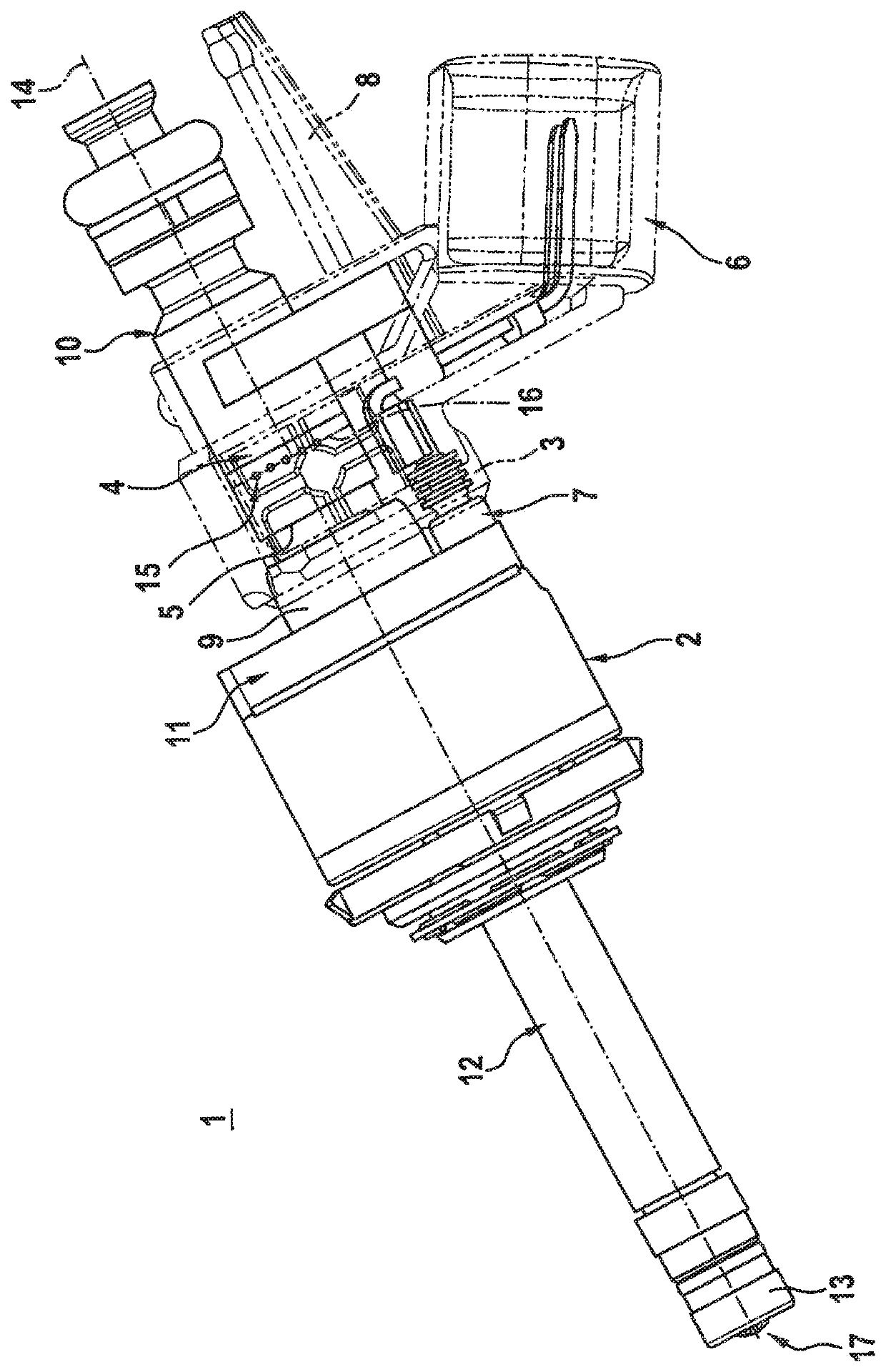
[0016]FIG. 1 shows a valve 1 for metering a fluid. Valve 1 is preferably used for metering a fuel, in particular gasoline or a fuel containing gasoline. Here, valve 1 can be fashioned as high-pressure injection valve 1, in particular as high-pressure fuel injection valve 1.

[0017]Valve 1 has a valve housing 2 and an extrusion coating 3. Extrusion coating 3 here surrounds an outer side 4 of a housing part 5 of valve housing 2. On extrusion coating 3 there is made a terminal 6 for a solenoid 7 and a rotational fixing 8. The rotational fixing 8 is fashioned as a part of extrusion coating 3 in this exemplary embodiment. In a modified embodiment, rotational fixing 8 can also be formed completely or partly from an additional element inserted into extrusion coating 3. In this way, the rotational fixing is joined to extrusion coating 3 on housing part 5.

[0018]In this exemplary embodiment, extrusion coating 3 also partly surrounds an inner pole 9 and a connecting sleeve 10 that form further h...


PUM


Abstract

A valve is used to meter a fluid. The valve can be fashioned in particular as a fuel injection valve for internal combustion engines. The valve has a housing part that is surrounded on its outer side by an extrusion coating. On the outer side of the housing part there is fashioned at least one recess into which the extrusion coating is at least partly introduced.

Description

CROSS REFERENCE[0001]The present application claims the benefit under 35 U.S.C. § 119 of German Patent Application No. DE 102015226452.1 filed on Dec. 22, 2015, which is expressly incorporated herein by reference in its entirety.FIELD[0002]The present invention relates to a valve for metering a fluid, in particular a fuel injection valve for internal combustion engines. Specifically, the present invention relates to the area of injectors for fuel injection systems of motor vehicles, in which preferably a direct injection of fuel into combustion chambers of an internal combustion engine takes place.BACKGROUND INFORMATION[0003]German Patent Application No. DE 199 50 761 A1 describes a fuel injection valve for fuel injection systems of internal combustion engines. The conventional fuel injection valve has a tubular valve seat bearer that can be introduced into a receptacle bore of a cylinder head of an internal combustion engine and is sealed against a receptacle bore of the cylinder h...

Claims


Application Information

Patent Timeline
Patent Type & Authority Patents(United States)
IPC IPC(8): F02M61/14F02M51/06F02M61/16F02M51/00
CPCF02M61/14F02M51/005F02M51/06F02M51/0625F02M61/168F02M2200/8015F02M2200/8046F02M2200/852F02M61/16F16K27/00
Inventor ITTLINGER, RALPH
Owner ROBERT BOSCH GMBH
Why Eureka
Try Eureka