
SGSN semi anchoring during the inter SGSN SRNC relocation procedure

a technology of sgsn and relocation procedure, which is applied in the direction of data switching networks, wireless communication, digital transmission, etc., can solve the problems of pdp context loss, data loss, and loss of qos, and achieve the effect of reducing the risk of data loss

Inactive Publication Date: 2005-06-21
RPX CORP
View PDF8 Cites 7 Cited by
  • Summary
  • Abstract
  • Description
  • Claims
  • Application Information

AI Technical Summary

Benefits of technology

[0017]Therefore, it is an object of the invention to provide a method for performing a relocation procedure for a user equipment UE communicating in a communication network and being movable therein, in which method the risk of data loss during a inter SGSN SRNC relocation procedure is minimized while the data flow is optimized after completion of the relocation, and to provide a corresponding system and network device adapted to perform such a relocation procedure.
[0022]According to the present invention, by using the proposed method and / or system and / or network element, the core network control remains advantageously in the same (first) serving node SGSN as long as there are packets to be sent. Consequently, a simple and robust relocation process is possible without a risk of loss of data. When it is most suitable for the user equipment (i.e. when the user equipment sends or receives no data), the control is changed to the new (second) serving node SGSN, which changing is initiated by the user equipment. This allows an optimization of the core network connectivity and therefore of the data flow for subsequent communications. Additionally, the user equipment can be simplified as it has only to know one instead of two procedures.

Problems solved by technology

However, the “floating” solution requires a very long and complex signaling procedure.
When the user equipment UE tries to perform a routing area update or attach procedure on returning to the coverage area, PDP contexts may therefore be lost.
Therefore, quality of service (QoS) may be affected.
However, there is another drawback.
This is particularly wasteful for communication network resources, especially when the PDP context last for a long time (hours or even days).

Method used


Image

  • SGSN semi anchoring during the inter SGSN SRNC relocation procedure
  • SGSN semi anchoring during the inter SGSN SRNC relocation procedure
  • SGSN semi anchoring during the inter SGSN SRNC relocation procedure

Examples


Embodiment Construction

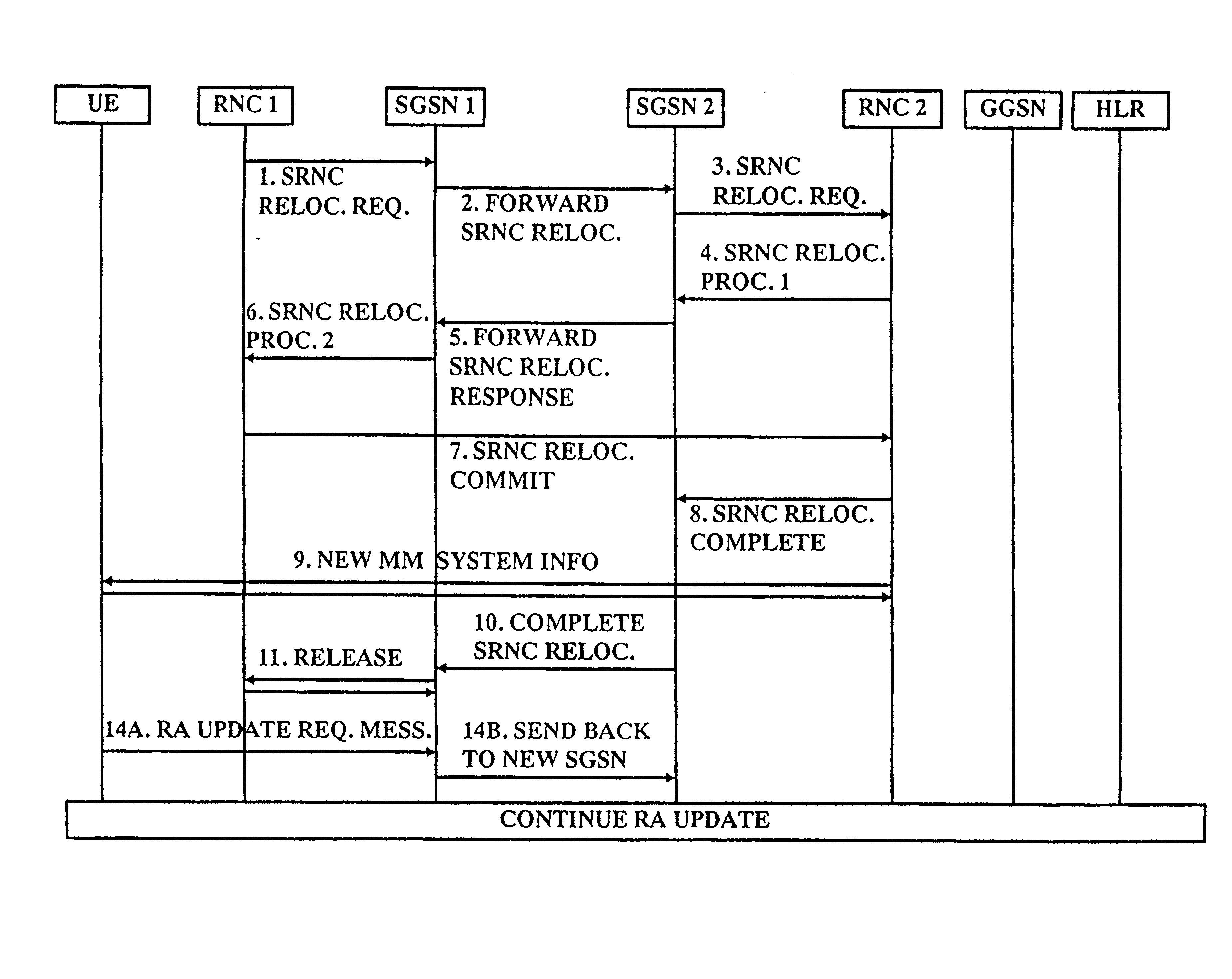
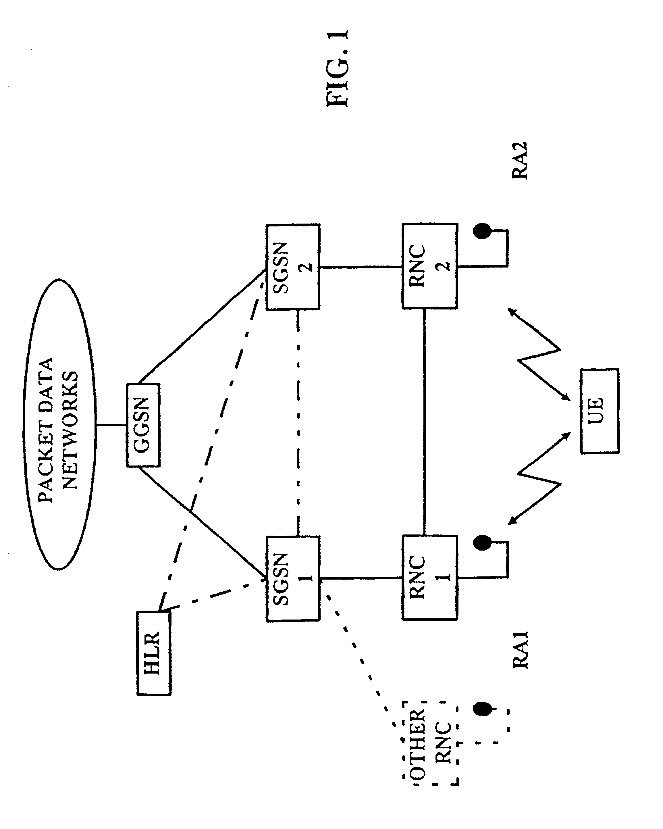
[0029]In FIG. 1 a simplified structure of a packet switched network system and the corresponding network elements is shown. An user equipment UE is moved within this system from one communication area or cell (not shown) to another, one or more of said communication areas being controlled by a radio network controller RNC. A routing area RA consists of one or more areas covered by radio network controllers. The radio network controllers RNC within one routing area RA are served by one serving node SGSN (Serving GPRS Support Node). The serving node SGSN is connected to a gateway node GGSN (Gateway GPRS Support Node) which provides connection to external networks.

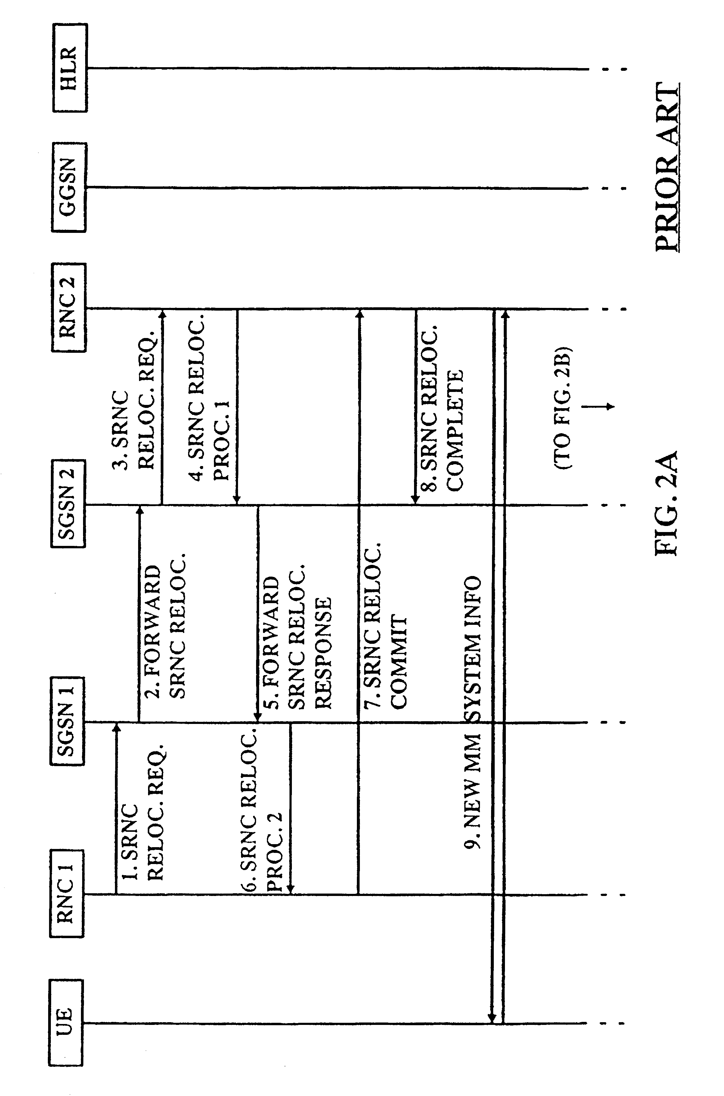
[0030]When the user equipment UE moves from a communication area covered by a first radio network controller RNC1 to a communication area covered by another radio network controller (for example other RNC or RNC2, as shown in FIG. 1), a serving radio network controller (SRNC) relocation procedure is executed. This procedure i...


PUM


Abstract

The present invention proposes a method for performing a relocation procedure for a user equipment (UE) communicating in a communication network and being movable therein, said communication network comprising at least two serving nodes (SGSN1, SGSN2) of a core network of said communication network, each of which serving nodes being connected to at least one access network controller (RNC1, RNC2) of a access network of said communication network, each of which access network controllers being adapted to perform a communication with said user equipment (UE) within its coverage area, and each serving node being assigned to a respective routing area (RA1, RA2), said method comprising the steps of monitoring (S100) the occurrence of a relocation condition, deciding (S200), whether said relocation condition is an inter serving node relocation condition, switching (S400) the communication from a first access network controller (RNC1) of a first serving node (SGSN1) to a second access network controller (RNC2) of a second serving node (SGSN2), when the decision in said decision step (S200) is positive; maintaining (S600) the control of communication in the core network anchored in the first serving node (SGSN1) while the communication connection is in a first state (S500); and changing (S700) the control of communication in the core network to the second serving node (SGSN2), when a changing condition is detected (S500). The present invention also proposes a corresponding system and network element.

Description

[0001]This application is a continuation of international application service No. PCT / EP99 / 02965, filed Apr. 30, 1999.FIELD OF THE INVENTION[0002]The present invention relates to a method for performing a relocation procedure for a user equipment communicating in a communication network and being movable therein, wherein the relocation initiated by said user equipment is to be performed between radio network controllers and between serving nodes. The present invention relates also to a corresponding system and network element. In particular, the present invention is directed to a method and a corresponding system and network element for semi anchoring control in a first serving node during an inter serving node relocation procedure.BACKGROUND OF THE INVENTION[0003]In recent years, the usage of mobile telecommunication systems for receiving and transmitting data packets becomes more and more important. In order to reach high transmission rates and better resource utilization in compa...

Claims


Application Information

Patent Timeline
IPC IPC(8): H04Q7/38H04Q7/22H04W36/12
CPCH04W36/12
Inventor EINOLA, HEIKKIHAUMONT, SERGESITCH, PAULRAJANIEMI, JAAKKO
Owner RPX CORP
Learn More