Vehicle control system and method

a control system and vehicle technology, applied in the field of vehicles, can solve the problems of loss or temporary interruption of data being transmitted to and/or from an electronic module, failure conditions in any one of a number of components in the control network or associated components, and high probability of failure,

a control system and vehicle technology, applied in the field of vehicles, can solve the problems of loss or temporary interruption of data being transmitted to and/or from an electronic module, failure conditions in any one of a number of components in the control network or associated components, and high probability of failure,

US6909944B2Inactive Publication Date: 2005-06-21OSHKOSH CORPORATION

Image

  • Vehicle control system and method
  • Vehicle control system and method
  • Vehicle control system and method

Examples


Embodiment Construction

A. Fire Truck Control System

[0026]For convenience, the contents of U.S. Ser. No. 09 / 364,690, upon which priority is claimed, are repeated below. The remainder of U.S. Ser. No. 09 / 364,690 that is not repeated below is hereby incorporated by reference.

1. Architecture of Preferred Fire Truck Control System

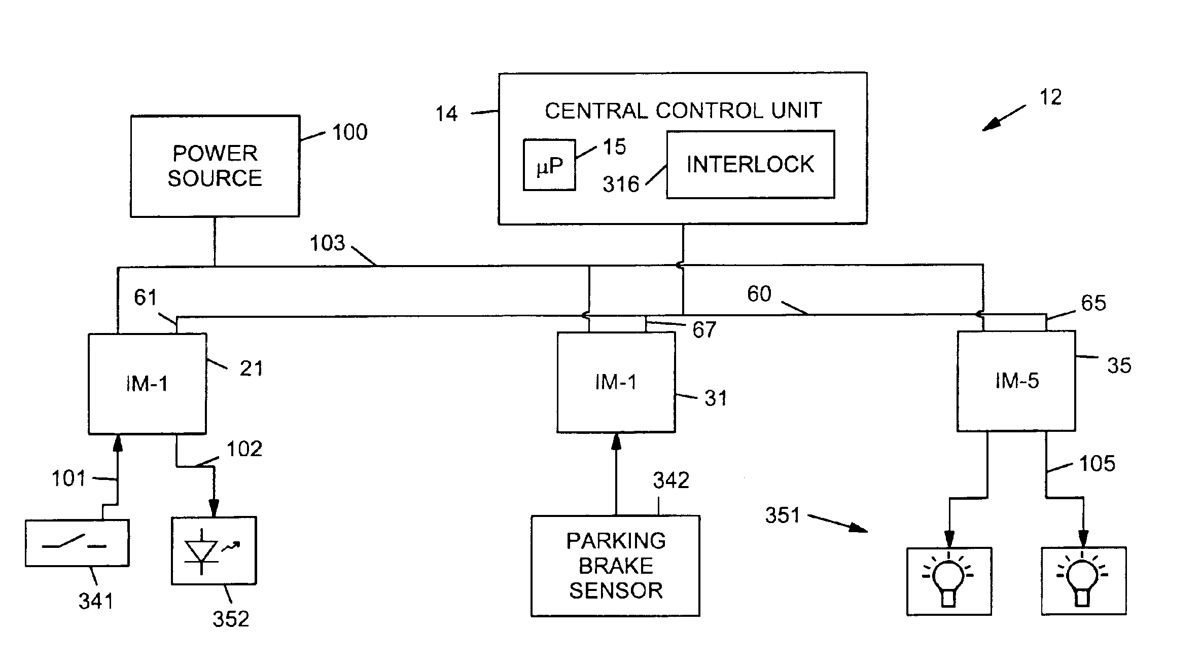
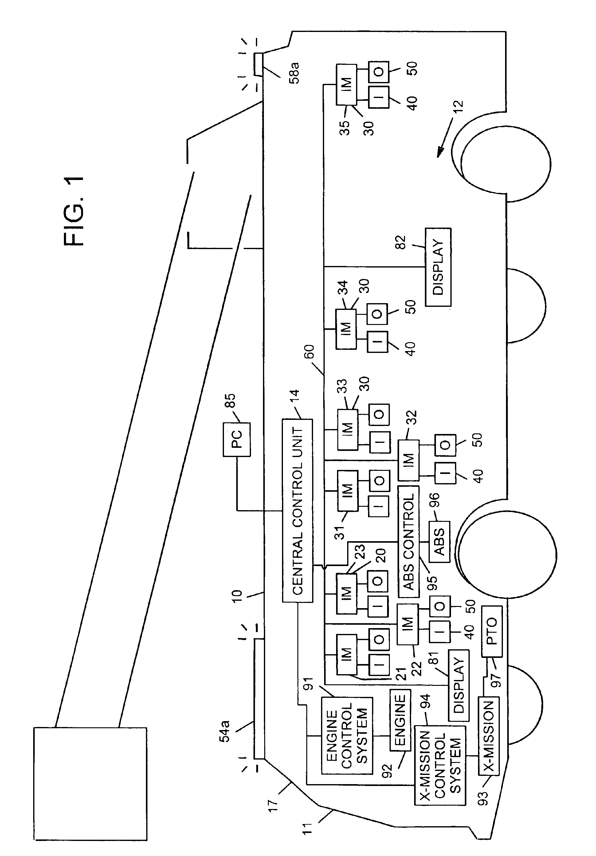
[0027]Referring now to FIG. 1, a preferred embodiment of a fire truck 10 having a control system 12 is illustrated. By way of overview, the control system 12 comprises a central control unit 14, a plurality of microprocessor-based interface modules 20 and 30, a plurality of input devices 40 and a plurality of output devices 50. The central control unit 14 and the interface modules 20 and 30 are connected to each other by a communication network60.

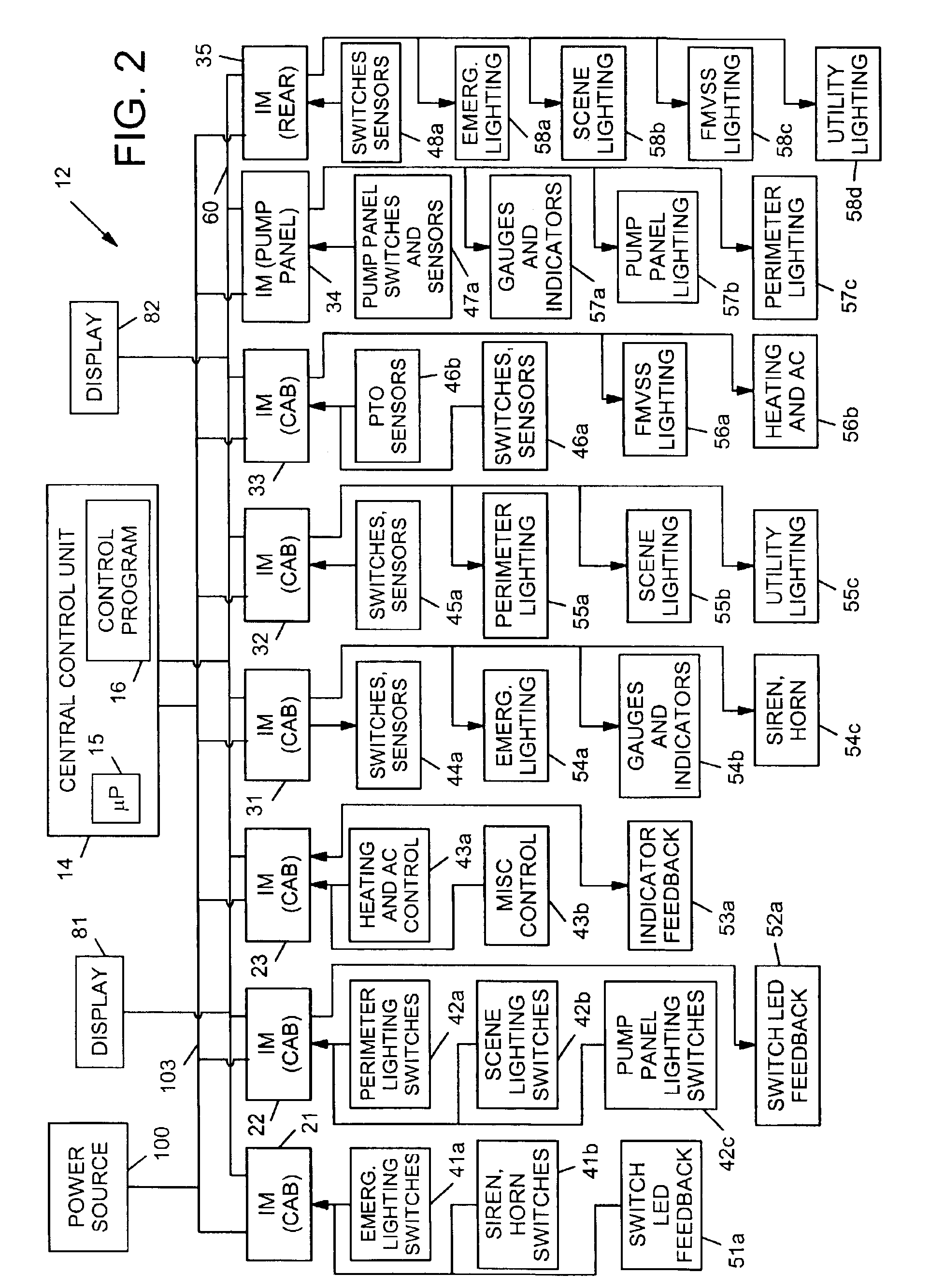
[0028]More specifically, the central control unit 14 is a microprocessor-based device and includes a microprocessor 15 that executes a control program 16 (see FIG. 2) stored in memory of the central control unit 14. The control program is sho...


PUM


Abstract

An interface module for a power distribution and control system for a vehicle is described. The interface module includes at least one first link configured to receive an input from input devices on the vehicle, at least one second link configured to control output devices on the vehicle, at least one third link configured to communicate with a communication network. The module further includes control logic configured to store a record of output devices associated with the interface module and to process a configuration file to determine whether any of the output devices have been designated as controlling a mission critical function.

Description

CROSS REFERENCE TO RELATED APPLICATIONS[0001]This application is a continuation-in-part of U.S. Ser. No. 09 / 927,946, pending, filed Aug. 10, 2001, which is a continuation-in-part of U.S. Ser. No. 09 / 384,393, filed Aug. 27, 1999, now U.S. Pat. No. 6,421,593, issued Jul. 17, 2002, which is a continuation-in-part of U.S. Ser. No. 09 / 364,690, filed Jul. 30, 1999, abandoned, all of which are hereby incorporated by reference.BACKGROUND OF THE INVENTION[0002]1. Field of the Invention[0003]The present invention relates to vehicles having interface modules in a control network with distributed I / O interfacing. In a particularly preferred aspect, the invention relates to a vehicle having interface modules in a control network with distributed I / O interfacing, wherein the interface modules are configured to maintain one or more outputs in the event of one or more failures in the control network.[0004]2. Description of Related Art[0005]Fire fighting vehicles, aircraft rescue and fire fighting (...

Claims


Application Information

Patent Timeline
21 Jun 2005
Publication
US6909944B2
IPC
B60R16/02; B65F3/02; B65F3/04; B60R16/03
CPC
B60R16/0315; B65F3/045; B65F3/043
Inventors
PILLAR, DUANE R.; MARTIN, PATRICK D.