Clothes drying cabinet with improved air distribution

a drying cabinet and air distribution technology, applied in the direction of drying machines, dryers, clothes, etc., can solve the problems that conventional drying cabinets generally do not provide a balanced air flow through the cabinet, and achieve the effect of enhancing the drying of objects laid on the shelves and constant air flow velocity

Inactive Publication Date: 2005-06-28
MAYTAG
View PDF60 Cites 40 Cited by
  • Summary
  • Abstract
  • Description
  • Claims
  • Application Information

AI Technical Summary

Benefits of technology

[0012]A clothes drying cabinet has a compartment with a front door or doors, opposite side walls, a rear wall, a top wall, and a bottom wall. A plurality of air inlet holes or nozzles are provided in one of the walls. An air plenum resides behind the air nozzles to distribute air from an air source through the nozzles and into the compartment for drying clothes therein. The air plenum has a cross sectional area which decreases from the nozzles closest to the air source to the nozzles furthest from the air source, so as to provide a substantially constant air flow velocity through the nozzles into the compartment. The nozzles are directed in an angular, non-horizontal orientation so as to provide drying air in multiple directions into the compartment. Mesh shelves may be provided in the compartment, with the air being directed to both the upper and lower surfaces of the shelves to enhance drying of objects laid on the shelves.

Problems solved by technology

However, conventional drying cabinets generally do not provide a balanced air flow through the cabinet, since the velocity of air flow through the inlet holes or louvers is greatest near the air supply source and progressively decreases as the inlet holes or louvers are spaced farther from the air supply source.

Method used


Image

  • Clothes drying cabinet with improved air distribution
  • Clothes drying cabinet with improved air distribution
  • Clothes drying cabinet with improved air distribution

Examples


Embodiment Construction

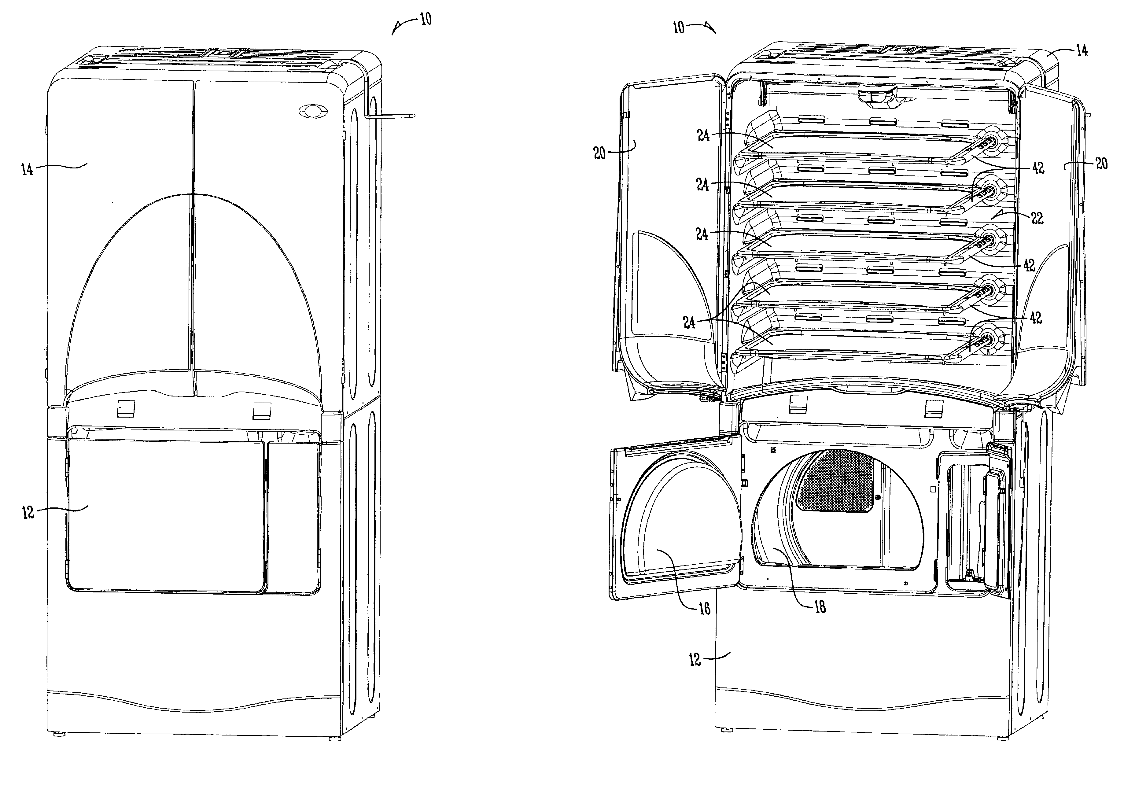
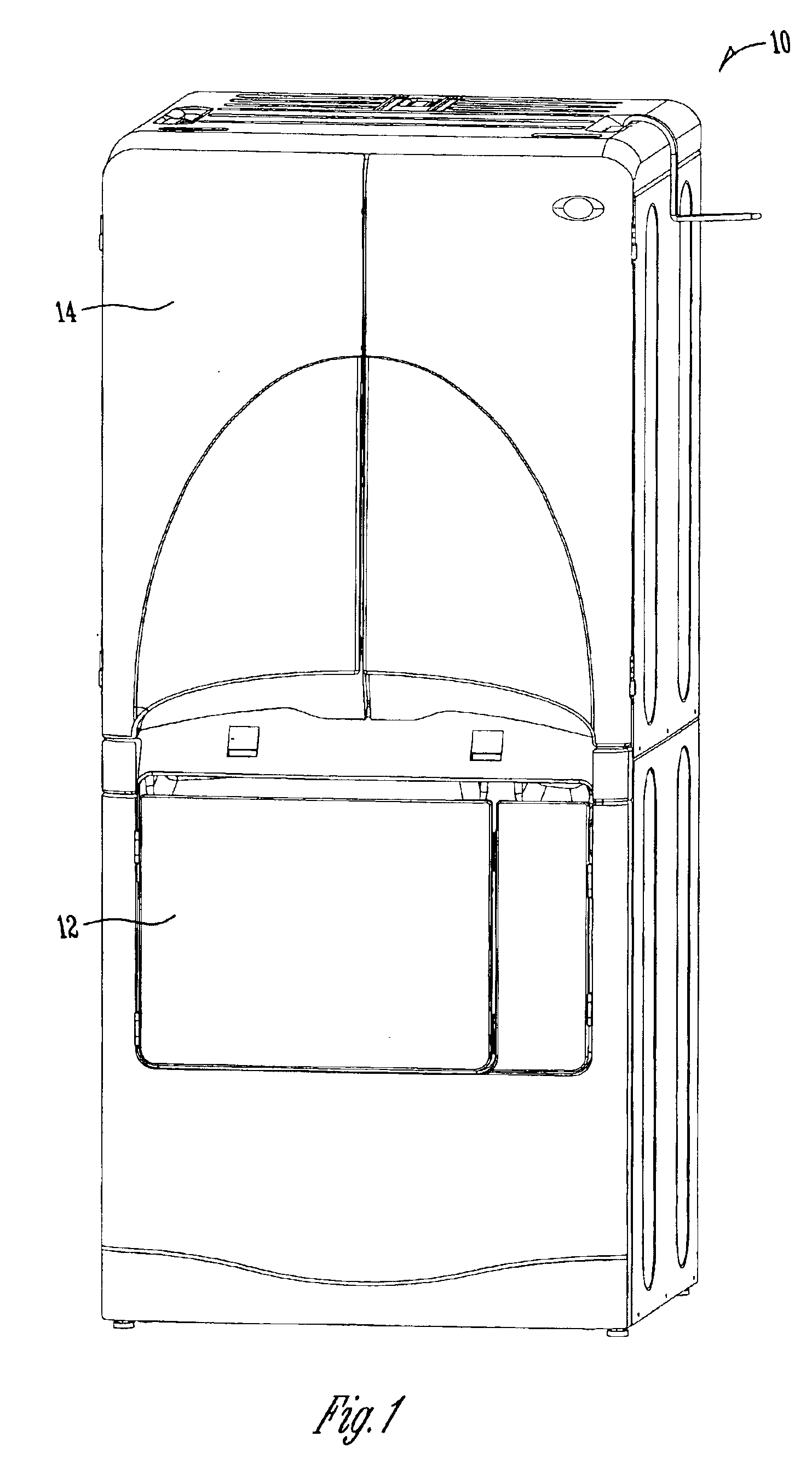
[0024]FIG. 1 shows a combination clothes drying machine 10 having a tumble dryer 12 and a drying cabinet 14. The drying cabinet 14 is shown to be mounted on top of the tumble dryer 12, though it is understood that other configurations can be provided. The tumble dryer 12 includes a door to provide access to the rotatable drum 18.

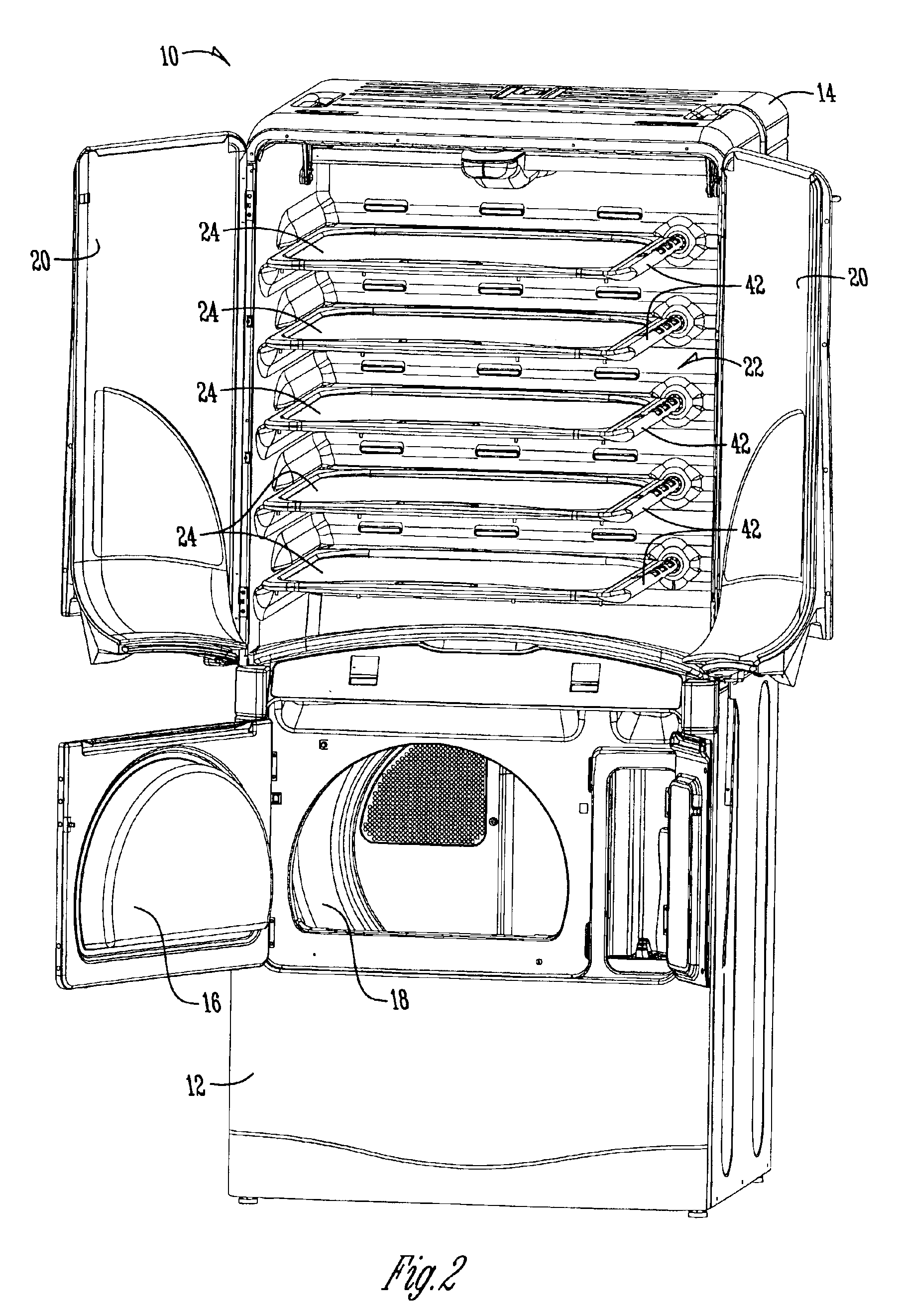
[0025]The drying cabinet 14 includes a pair of doors 20 which provide access to a drying compartment 22. As seen in FIG. 2, the compartment 22 may include removable shelves 24, which preferably have a mesh support surface so that air can circulate therethrough.

[0026]The compartment 22 is formed by a liner 26, best shown in FIG. 3. The liner 26 includes opposite side walls 28, 30, a rear wall 32, a top wall 34, and a bottom wall 36. The bottom wall 36 has a curved profile so as to extend around the drum 18 of the tumble dryer 12. The compartment 22 includes an elongated portion 38 adapted to receive long hanging items for drying, such as a dress.

[0027]A plura...


PUM


Abstract

A clothes drying cabinet is provided with an internal compartment for receiving clothes and having a plurality of air inlet nozzles. An air plenum provides air to the cabinet through the nozzles. The plenum has a decreasing cross section from one corner to an opposite corner to provide a balanced distribution of air through the nozzles at a substantially uniform velocity. The nozzles are angularly oriented to direct air across upper and lower surfaces of shelves mounted within the drying compartment.

Description

BACKGROUND OF THE INVENTION[0001]Clothes drying cabinets, which are more common in Japan than in the United States, are used for drying clothes without the conventional tumbling action. As opposed to a conventional tumbler dryer, a drying cabinet provides heated air for drying clothes hanging in the cabinet. Drying cabinets can also be used for de-wrinkling clothes. The de-wrinkling process includes the introduction of steam into the cabinet, which facilitates the removal of wrinkles from the clothes. The drying air is provided through multiple holes or louvers formed in one or more walls of the drying cabinet. However, conventional drying cabinets generally do not provide a balanced air flow through the cabinet, since the velocity of air flow through the inlet holes or louvers is greatest near the air supply source and progressively decreases as the inlet holes or louvers are spaced farther from the air supply source. Also, the drying air normally enters the cabinet through the hol...

Claims


Application Information

Patent Timeline
Patent Type & Authority Patents(United States)
IPC IPC(8): D06F58/10D06F71/00D06F71/34
CPCD06F58/10
Inventor PROWS, DENNIS S.
Owner MAYTAG
Why Eureka
Try Eureka