Liquid ejecting apparatus

a liquid ejecting and apparatus technology, applied in the direction of printing, inking apparatus, etc., can solve the problems of clogging of the nozzle opening, causing unstable ejection, affecting etc., to reduce the temperature, reduce the durability of the liquid ejecting head, and suppress defective liquid ejection

Active Publication Date: 2010-09-30
SEIKO EPSON CORP
View PDF2 Cites 14 Cited by
  • Summary
  • Abstract
  • Description
  • Claims
  • Application Information

AI Technical Summary

Benefits of technology

[0013]According to an aspect of the invention, there is provided a liquid ejecting apparatus including: a liquid ejecting head having a nozzle opening for ejecting a liquid; a heating unit disposed opposite a liquid ejecting surface of the liquid ejecting head; a transporting unit that transports a liquid-ejection-target medium between the liquid ejecting head and the heating unit; and a blower unit that blows air onto a surface of the liquid-ejection-target medium. The blower unit is provided so as to be able to vary an amount of air blown in a plurality of regions disposed along a certain direction, the plurality of regions including a region of the liquid-ejection-target medium. Furthermore, the liquid ejecting apparatus has a blowing control unit that controls an amount of the air blown from the blower unit in the plurality of the regions disposed along the certain direction on the basis of a width of the medium in the certain direction. In the aspect, the control of an amount of the air blown from the blower unit in the certain direction of the liquid-ejection-target medium leads to decreasing a temperature at which a predetermined liquid ejecting head is heated, so that it is possible to suppress defective liquid ejection and the decrease of the durability of the liquid ejecting head due to the application of heat to the liquid ejecting head. Because it is possible to decrease a temperature at which a predetermined liquid ejecting head is heated without decreasing a temperature at which the heating unit heats the liquid-ejection-target medium, it is possible to advance drying of ejected ink with the heating unit and the blower unit, so that it is possible to improve print quality.
[0014]It is preferable that the blowing control unit controls the blower unit so as to increase an amount of air blown in a region in which the liquid-ejection-target medium does not exist, relative to an amount of the air blown in a region in which the liquid-ejection-target medium exists. By virtue of this advantage, it is possible to decrease a temperature at which the liquid ejecting head, which has tendency to increase viscosity of a liquid in the vicinity of the nozzle opening and is not used for liquid ejection, is heated.
[0015]It is preferable that the liquid ejecting apparatus has an air heating unit that heats air blown from the blower unit, and that the air heating unit is disposed in every region in which it is possible to vary an amount of the air blown from the blower unit so as to be able to vary a temperature at which air is heated, and that the temperature at which the air heating unit heats air is in inverse proportion to an amount of the air blown from the blower unit in each of the region. By virtue of this advantage, it is possible to set a temperature at which a small amount of blown air is heated so as to be high to advance drying of a liquid applied to the liquid-ejection-target medium, and it is possible to set a temperature at which a large amount of blown air is heated so as to be low to decrease a temperature at which a predetermined liquid ejecting head is heated.
[0016]It is preferable that a plurality of the nozzle openings are formed along the certain direction of the liquid-ejection-target medium. By virtue of this advantage, it is possible to decrease a temperature at which a vicinity of the nozzle opening not used for liquid ejection is heated.
[0017]It is preferable that a plurality of the liquid ejecting heads are disposed along the certain direction of the liquid-ejection-target medium. By virtue of this advantage, it is possible to perform printing all over a broad range in a short time in a certain direction of the liquid-ejection-target medium without enlarging size of the liquid ejecting head itself. Furthermore, it is possible to decrease a temperature at which the liquid ejecting head not used for liquid ejection is heated.
[0018]It is preferable that the certain direction of the liquid-ejection-target medium is a direction intersecting a direction of relative movement between the liquid ejecting head and the liquid-ejection-target medium. By virtue of this advantage, it is possible to decrease a temperature at which a vicinity of the nozzle opening not used for liquid ejection is heated in a direction intersecting the direction of the relative movement between the liquid ejecting head and the liquid-ejection-target medium.

Problems solved by technology

Thereby, viscosity of the ink in the vicinity of the nozzle opening is increased, leading to a risk that unstable ejection will be caused due to the thickened ink.
In addition, there is a disadvantage that further drying of the ink causes clogging of the nozzle opening.
Furthermore, dust is adhered to the ink, so that the ink is adhered as a foreign object in the vicinity of the nozzle opening, resulting in disadvantages such as clogging of the nozzle opening and defective liquid ejection, that is, it is difficult to eject an ink droplet in a predetermined direction when ejection has started.
Furthermore, in cases where the ink jet recording head is heated, an adhesive adhering to each member configuring the ink jet recording head is degraded due to variation in the coefficient of thermal expansion of each member, or the heat helps a solvent contained in ink to degrade of a component of the recording head and the adhesive.
Consequently, there is a disadvantage that durability of the ink jet recording head is decreased.
Such disadvantages are not limited to ink jet recording apparatuses, but similarly exist in liquid ejecting apparatuses for ejecting liquids other than ink.

Method used


Image

  • Liquid ejecting apparatus
  • Liquid ejecting apparatus
  • Liquid ejecting apparatus

Examples


first embodiment

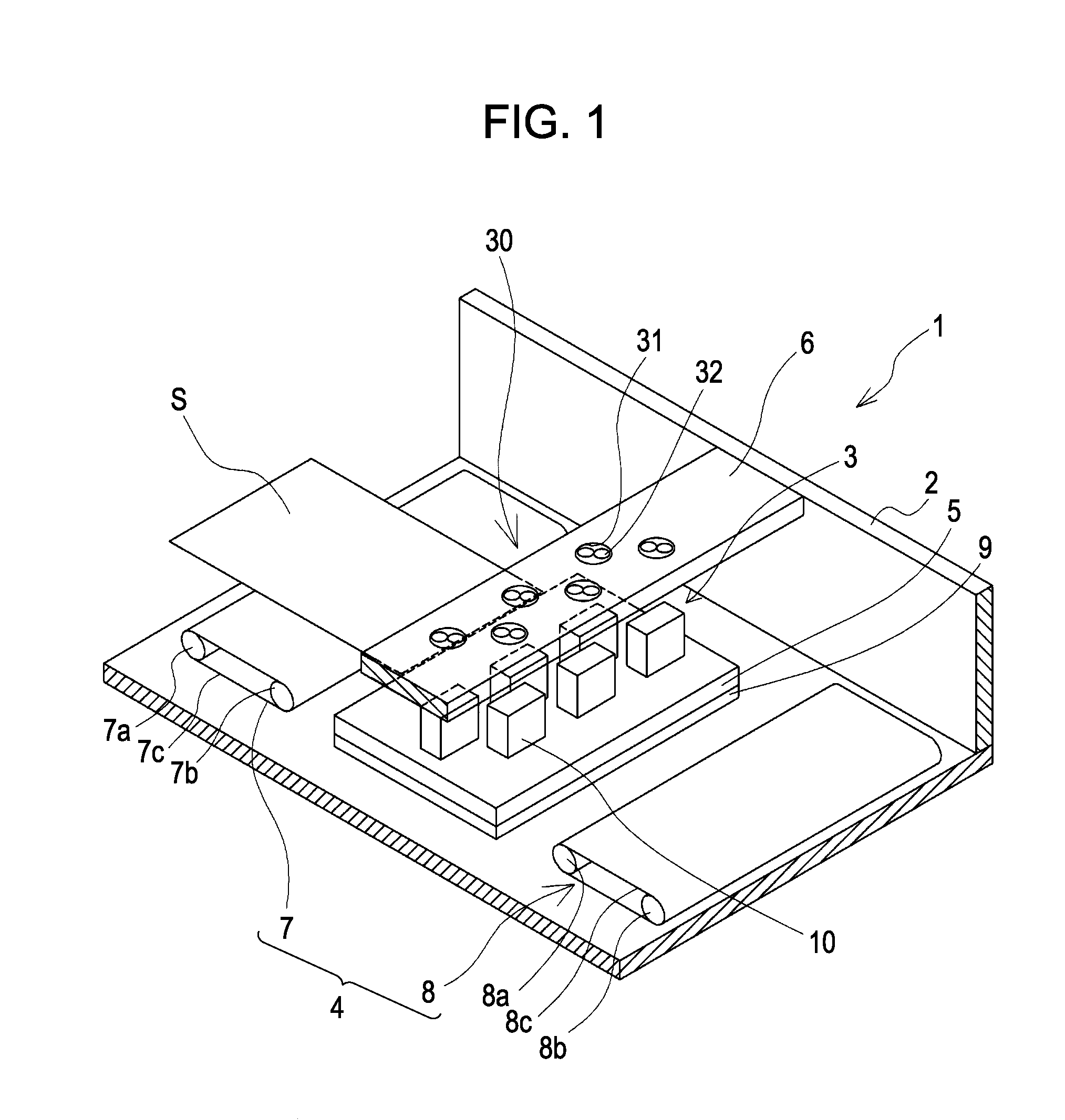
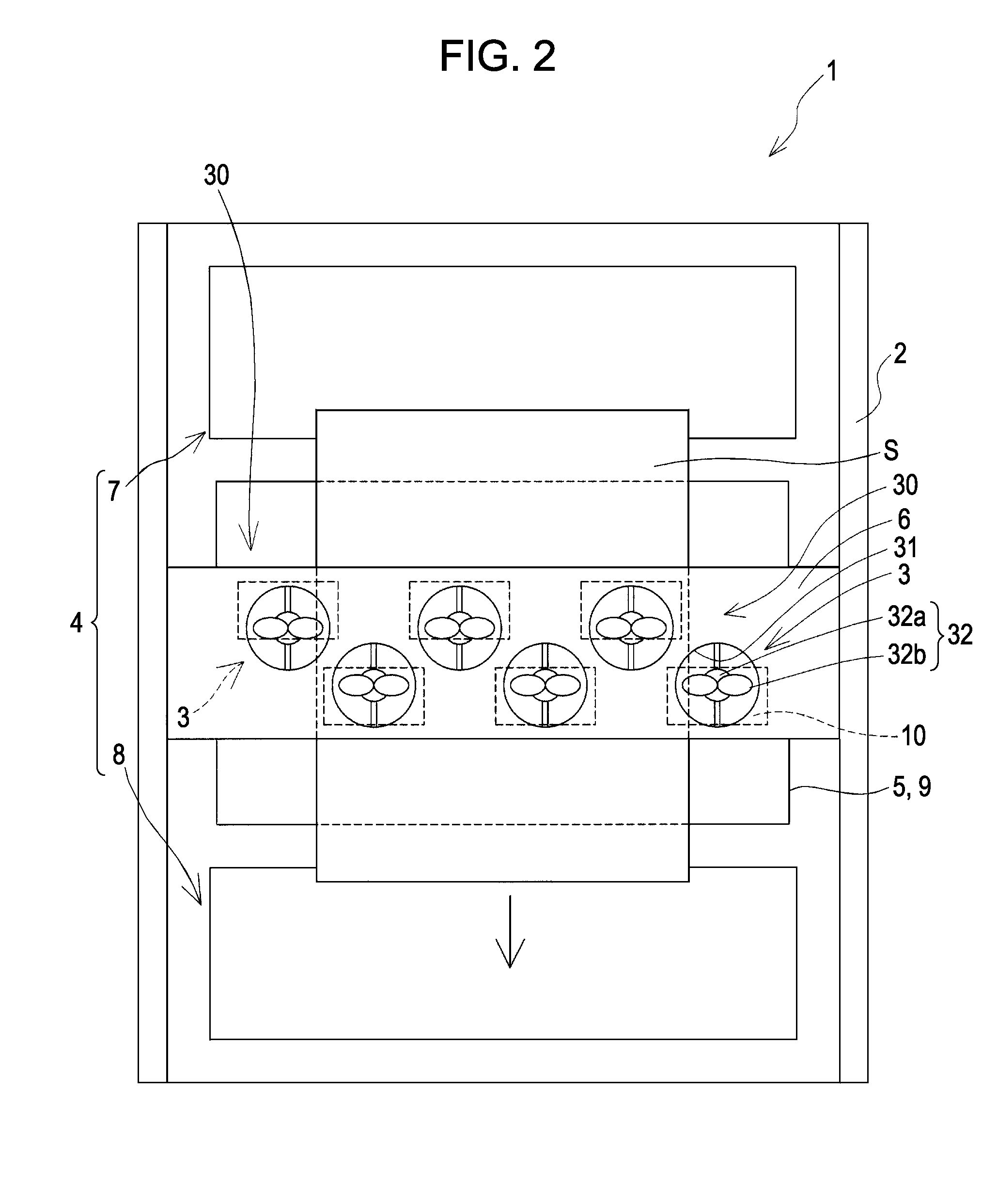
[0034]FIG. 1 is a perspective view schematically illustrating an ink jet recording apparatus as an example of a liquid ejecting apparatus according to a first embodiment of the invention. FIG. 2 is a top view illustrating the ink jet recording apparatus. FIG. 3A is a cross sectional view illustrating the ink jet recording apparatus in a transport direction of a recording medium. FIG. 3B is a cross sectional view illustrating the ink jet recording apparatus in a direction intersecting the transport direction of a recording medium.

[0035]As shown in the figures, an ink jet recording apparatus 1 as an example of a liquid ejecting apparatus of the embodiment is a so-called line recording apparatus in which an ink jet recording head is fixed therein and a recording sheet S such as paper as a liquid-ejection-target medium is transported to perform printing. Specifically, the ink jet recording apparatus 1 includes a body 2, a plurality of ink jet recording heads 10, a head unit 3 fixed to t...

second embodiment

[0079]FIG. 8 is a cross sectional view illustrating a blower unit and an air heating unit according to a second embodiment of the invention. In addition, the same member as the first embodiment is denoted by the same number, and repetitive description is omitted.

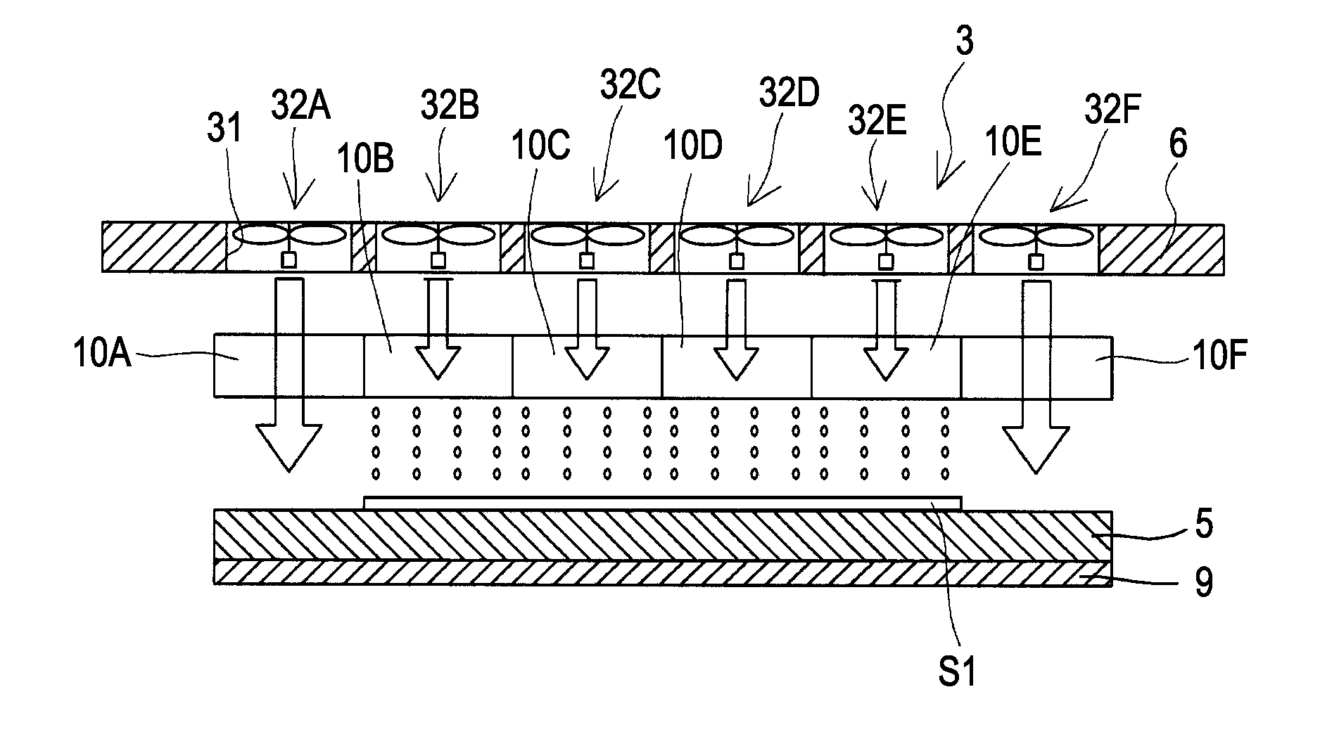
[0080]With reference to FIG. 8, in the embodiment, the blower unit 30 is provided with an air heating unit 40 that heats air blown from the blower unit 30. Specifically, heating sections 41A to 41F as the air heating unit 40 are individually provided in each of the blowing holes 31 of the holding section 6.

[0081]The individual heating sections 41A to 41F are disposed below each blowing device 32A to 32F in the individual blowing holes 31. Air blown from the blowing devices 32A to 32F respectively contacts the heating sections 41A to 41F, so that the air is heated. It is possible to use an electrothermal heater as the heating sections 41A to 41F.

[0082]In the embodiment, the individual heating sections 41A to 41F as the air he...

third embodiment

[0084]FIGS. 9A and 9B are partial perspective views illustrating an ink jet recording apparatus according to a third embodiment of the invention. In addition, the same member as the first embodiment is denoted by the same number, and repetitive description is omitted.

[0085]With reference to FIG. 9A, in the embodiment, a suction unit 50 is provided at a position facing liquid ejecting surfaces (surfaces on which the nozzle openings 13 are respectively formed) of the ink jet recording heads 10A to 10F, the suction unit 50 suctioning the recording sheet S in a direction opposite to the ink jet recording heads 10A to 10F.

[0086]The suctioning unit 50 of the embodiment includes a plurality of suctioning holes 51 formed on the supporting section 5, and suctioning devices 52A to 52F (hereinafter referred to as suctioning devices 52) individually provided in each of the suctioning holes 51.

[0087]The suctioning holes 51 are formed on a surface of the supporting section 5 that supports the rec...


PUM


Abstract

A liquid ejecting apparatus includes: a liquid ejecting head having a nozzle opening for ejecting a liquid; a heating unit disposed opposite a liquid ejecting surface of the liquid ejecting head; a transport unit that transports a liquid-ejection-target medium between the liquid ejecting head and the heating unit; a blower unit that blows air onto a liquid-ejection-target surface of the medium; and a blowing control unit. The blower unit is able to vary an amount of air blown in a plurality of regions disposed along a certain direction, the plurality of regions including a region of the liquid-ejection-target medium, and the blowing control unit controls an amount of the air blown from the blower unit in the plurality of the regions along the certain direction on the basis of a width of the medium in the certain direction.

Description

BACKGROUND[0001]1. Technical Field[0002]The present invention relates to a liquid ejecting apparatus including a liquid ejecting head for ejecting a liquid onto a liquid-ejection-target medium.[0003]2. Related Art[0004]An ink jet recording apparatus such as an ink jet printer or a plotter has an ink jet recording head which is capable of ejecting ink as an ink droplet, the ink being stored in a storage unit such as an ink cartridge or an ink tank.[0005]The ink jet recording head has a pressure generating chamber that is in communication with a nozzle opening and a pressure generating unit for generating a pressure change in the pressure generating chamber to eject an ink droplet from the nozzle opening. Examples of the pressure generating unit mounted on the ink jet recording head include a longitudinal vibration type piezoelectric device, a flexural vibration type piezoelectric device, a heat generating device, and a unit using electrostatic force.[0006]In JP-A-2004-223962 and JP-A...

Claims


Application Information

Patent Timeline
Patent Type & Authority Applications(United States)
IPC IPC(8): B41J2/01
CPCB41J2/14274B41J2202/20B41J2202/08B41J2/155
Inventor IHARA, SEIJI
Owner SEIKO EPSON CORP
Why Eureka
Try Eureka