Pliers head for pressing work pieces

Active Publication Date: 2005-06-28
WEZAG - WERKZEUGFAB
View PDF5 Cites 14 Cited by
  • Summary
  • Abstract
  • Description
  • Claims
  • Application Information

AI Technical Summary

Benefits of technology

[0007]The present invention also relates to a pliers head for pressing work pieces including a stationary die and a movable die. The stationary die and the movable die are associated with one another to form at least one nest being designed and arranged for receiving a work piece to be pressed. The pliers head also includes a housing. The housing is designed to be comparatively stiff. The housing is designed and arranged to support the movable die in a way that the movable die is movable in a linear direction towards and away from the stationary die. A lever is connected to the stationary die. The lever and the housing are designed as separate parts, and they are designed and arranged to form a C-shaped mouth in which the dies are located. A joint is designed and arranged to connect the housing and the lever in a way that the lever may be pivoted with respect to the housing about the joint. A stop is designed and arranged to limit pivotal movement of the lever with respect to the housing. A resilient element is designed and arranged to supply pretensional torque to the lever. The pretensional torque counteracts pressing torque resulting from a movement of the movable die towards the stationary die. In this way, the resilient element and the stop are designed and arranged to secure a parallel position of the first and second die with respect to one another.
[0008]The present invention is based on the concept of designing the C-shaped mouth of the pliers head to include two separate elements of which one is connected to the first die and the other is connected to the second die. The dies are located at the legs of the C-shaped mouth to be replaceable. The first element is designed as a housing being comparatively stiff to bending. The second element is supported at the first element by a joint to be pivoted about the axis of the joint. In this way, the second element with its die may be moved with respect to the first element about the joint. This movement is limited by a stop. The stop ensures the parallel position of the dies during the pressing or crimping operation.
[0009]For this purpose, the pivotable second element is designed as a lever which may be subjected to pretension. The lever may be subjected to tension the value of which approximately corresponds to the value of the maximum pressing force. When the pretensional force is slightly less than the maximum pressing force, there will still be a small part at the end of the pressing stroke at which there are small resilient effects. The lever is put under pretension against the securing stop. The pressing force counteracts the pretensional force during the pressing operation such that the pretensional force is “consumed” when the pressing operation continues. The lever does not move. Due to these effects, the parallel position of the dies may be maintained during the entire pressing operation, and undesired resilient effects of the C-shaped opening of the pliers head are effectively prevented.
[0011]The pretensional force being supplied to the lever produces pretensional torque about the axis of the joint of the lever in one sense of rotation such that a reaction force builds up at the stop which secures the parallel position of the dies. The reaction force produces reaction torque being directed in the opposite sense of rotation about the joint. The reaction torque has the same value as the pretensional torque. The reaction torque is taken over during the pressing operation by torque being produced by the pressing force acting upon the lever. In this way, the stop will be increasingly freed from subjection to forces during the pressing operation. It is ensured that the pretensioned lever maintains its parallel position, and thus the parallel position between the dies is maintained during the entire pressing operation.
[0014]There is the possibility of designing the lever to have an approximately perpendicular shape such that the two lever arms of the lever are arranged at an approximately right angle with respect to one another. In such a design, it is advantageous to design the lever arm which does not carry a die to be comparatively long, and to place it in the direction of main extension of the pliers and of the pliers head, respectively. When the stiff housing has a design including plates—meaning at least two cover plates—there is the possibility of also designing the lever to include plates being located between these cover plates in a safe and space-saving manner. The other lever arm which does carry a die may then be located within the pliers head in a transverse direction with respect to the direction of main extension of the pliers such that one attains an opening or a mouth which is similar to the known shape of such pliers and pliers heads, respectively. However, the novel pliers head does not require more space than known pliers heads. It is also possible to arrange the two lever arms at an angle of approximately 180°.

Problems solved by technology

In addition to the improvement concerning the linear guidance of the movable crimping die, it is also known from German Patent Application No. 198 07 737 A1 and U.S. Pat. No. 6,026,671 that pliers heads having a C-shaped mouth generally have the drawback of the correspondingly C-shaped cover plates showing resilient effects when great pressing forces are applied.
Despite the linear guidance of the movable pressing die, the two pressing dies reach an angled position which not only has a negative influence on the pressing quality, but which also leads to early wear and tear of the pressing dies.
Due to the resilient effects of the cover plates within a certain but limited angle, undesired pressing marks may occur in the nests of the dies.
These pressing marks result in undesired changes of the nests.
Especially in the case of hand driven tools such as hand operable pliers, the possibilities of increasing the mass in the region of the C-shaped opening and of designing a C-shaped mouth as a stiff and non-resilient body are limited.
In many cases, it is not possible to arrange stiffening plates in the pliers head since adjusting units and the like for determining the pressing position of the work piece are located in this region.

Method used


Image

  • Pliers head for pressing work pieces
  • Pliers head for pressing work pieces
  • Pliers head for pressing work pieces

Examples


Embodiment Construction

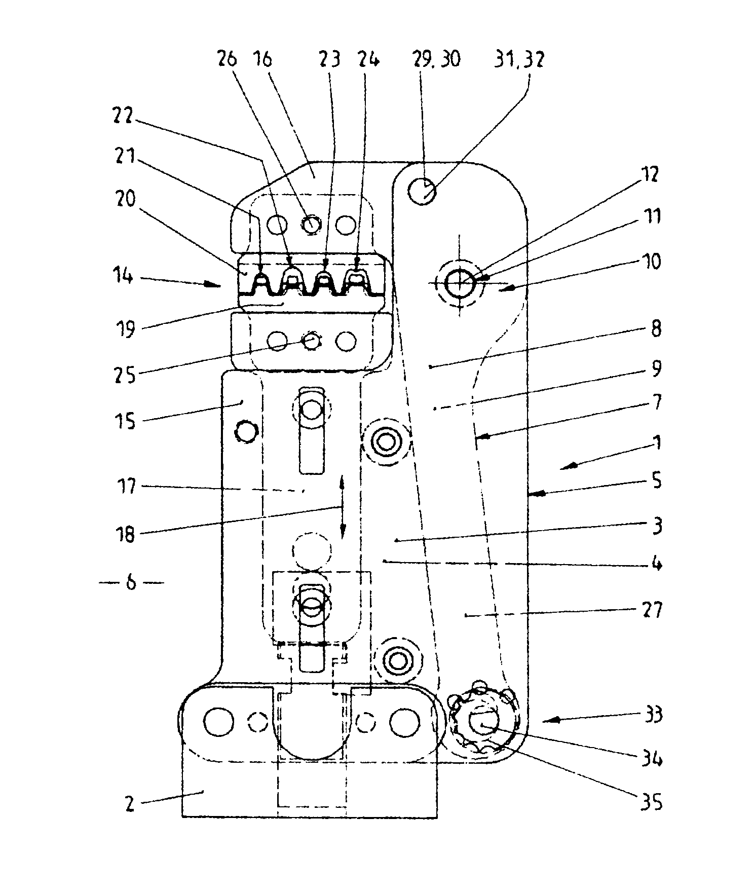
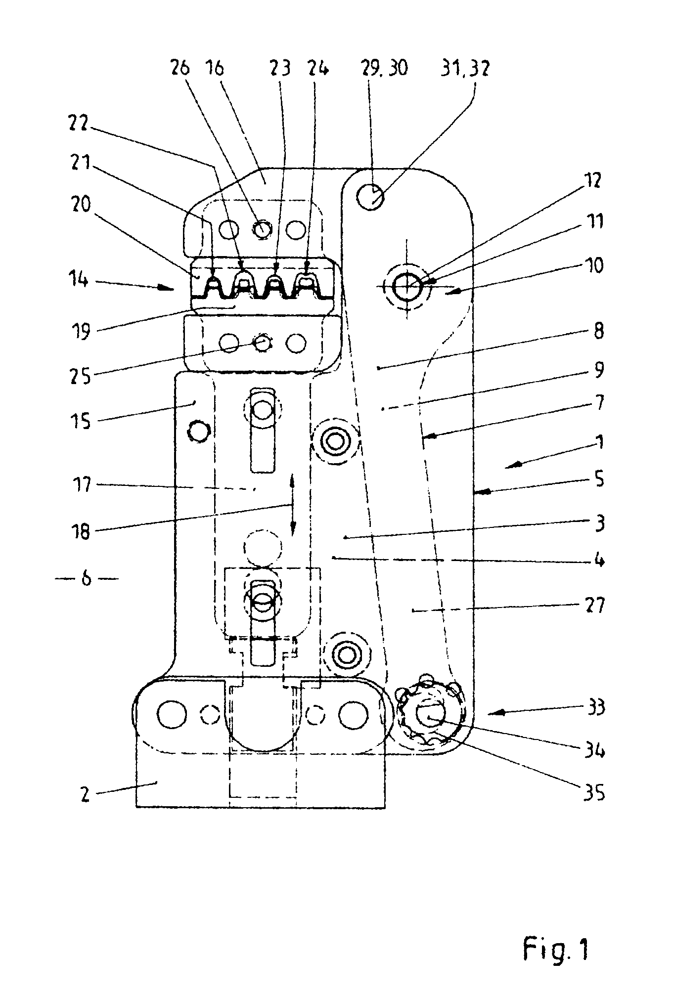
[0028]Referring now in greater detail to the drawings, FIG. 1 illustrates a novel pliers head 1. For example, the pliers head 1 may be connected to an electrically driven tool or an otherwise driven tool. For this purpose, the pliers head 1 includes a connecting element 2. The design and arrangement of the connecting element 2 is of no special importance to the present invention. Consequently, the connecting element 2 and the drive to be connected to the pliers head 1 by the connecting element 2 to form pliers are not explained in great detail. The design of the drive for the novel pliers head 1 may be conventional as known from the prior art.

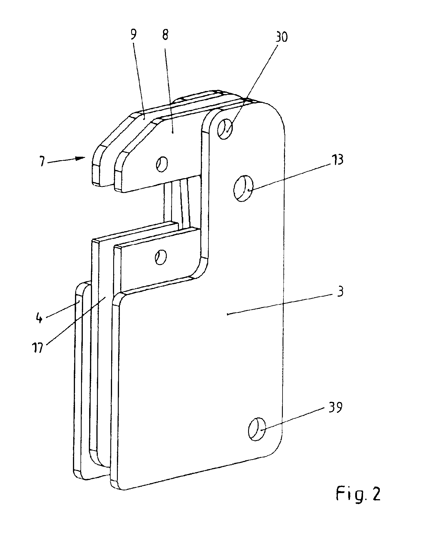
[0029]Two cover plates 3 and 4 are fixedly connected to the connecting element 2. The cover plates 3 and 4 together form a stiff housing 5. The design and arrangement of these cover plates 3 and 4 is chosen to result in a preferably stiff unit which is comparatively resistant to bending. The two cover plates 3 and 4 are arranged to be symmetric...


PUM

PropertyMeasurementUnit
Forceaaaaaaaaaa
Shapeaaaaaaaaaa
Resilienceaaaaaaaaaa

Abstract

A pliers head (1) for pressing work pieces includes a stationary die (20) and a movable die (19). A first element (15) is designed as a comparatively stiff housing (5). A second element (16) is designed as a lever (7). The lever (7) is subjected to a pretensional force (36). The pretensional force (36) has at least the value of a predetermined maximum pressing force of the pliers head (1). The first and second element (15, 16) are designed as separate parts, and they form a C-shaped mouth (14). The dies (19, 20) are located in the C-shaped mouth (14). A joint (10) is located at the first element (15), and it allows for pivotal movement of the second element (16) with respect to the first element (15). A stop (32) secures a parallel position of the stationary die and the movable die with respect to one another. As a result, the resulting pretensional torque counteracts the pressing torque, and the parallel arrangement of the dies (19, 20) is maintained.

Description

CROSS REFERENCE TO RELATED APPLICATIONS[0001]This application claims priority to co-pending German Patent Application No. 102 42 345.8 entitled “Zangenkopf zum Verpressen eines Werkstücks”, filed Sep. 12, 2002.FIELD OF THE INVENTION[0002]The present invention generally relates to a pliers head for pressing work pieces. More particularly, the pliers head may serve to produce solderless crimping connections. However, it may also be used to simply deform work pieces. The pliers head may be part of pliers which are driven by hand, meaning which include two handles to be pivoted with respect to one another by the hand of the user. The pliers head may also be used in combination with an electric tool, a pneumatic tool or a hydraulic tool for driving the dies being located in the pliers head to conduct a pressing operation.BACKGROUND OF THE INVENTION[0003]Hand operable pliers including a pliers head are known from German Patent Application No. 198 07 737 A1 corresponding to U.S. Pat. No. 6...

Claims


Application Information

Patent Timeline
IPC IPC(8): B25B27/14H01R43/042H01R43/04
CPCB25B27/146H01R43/042Y10T29/53226
Inventor BEETZ, HORSTBATTENFELD, KURT
Owner WEZAG - WERKZEUGFAB
Why Eureka
Try Eureka