A bent axis hydrostatic module with multiple yokes

a technology of hydrostatic modules and yoke, which is applied in the direction of positive displacement liquid engines, fluid couplings, gearing, etc., can solve the problems of limited power output of devices, physical size, space and size, and achieve the effect of facilitating power transfer

Active Publication Date: 2006-01-12
DANFOSS POWER SOLUTIONS INC
View PDF10 Cites 10 Cited by
  • Summary
  • Abstract
  • Description
  • Claims
  • Application Information

AI Technical Summary

Benefits of technology

[0025] The configuration is unique in that two variable bent axis kits housed in single piece yokes are joined together in one package with shafts aligned in parallel axis. This arrangement facilitates the transfer of power in to and out of t

Problems solved by technology

Such devices have power output limited to their physical size.
However, space and size become a problem in certain vehicle designs and

Method used


Image

  • A bent axis hydrostatic module with multiple yokes
  • A bent axis hydrostatic module with multiple yokes
  • A bent axis hydrostatic module with multiple yokes

Examples


Embodiment Construction

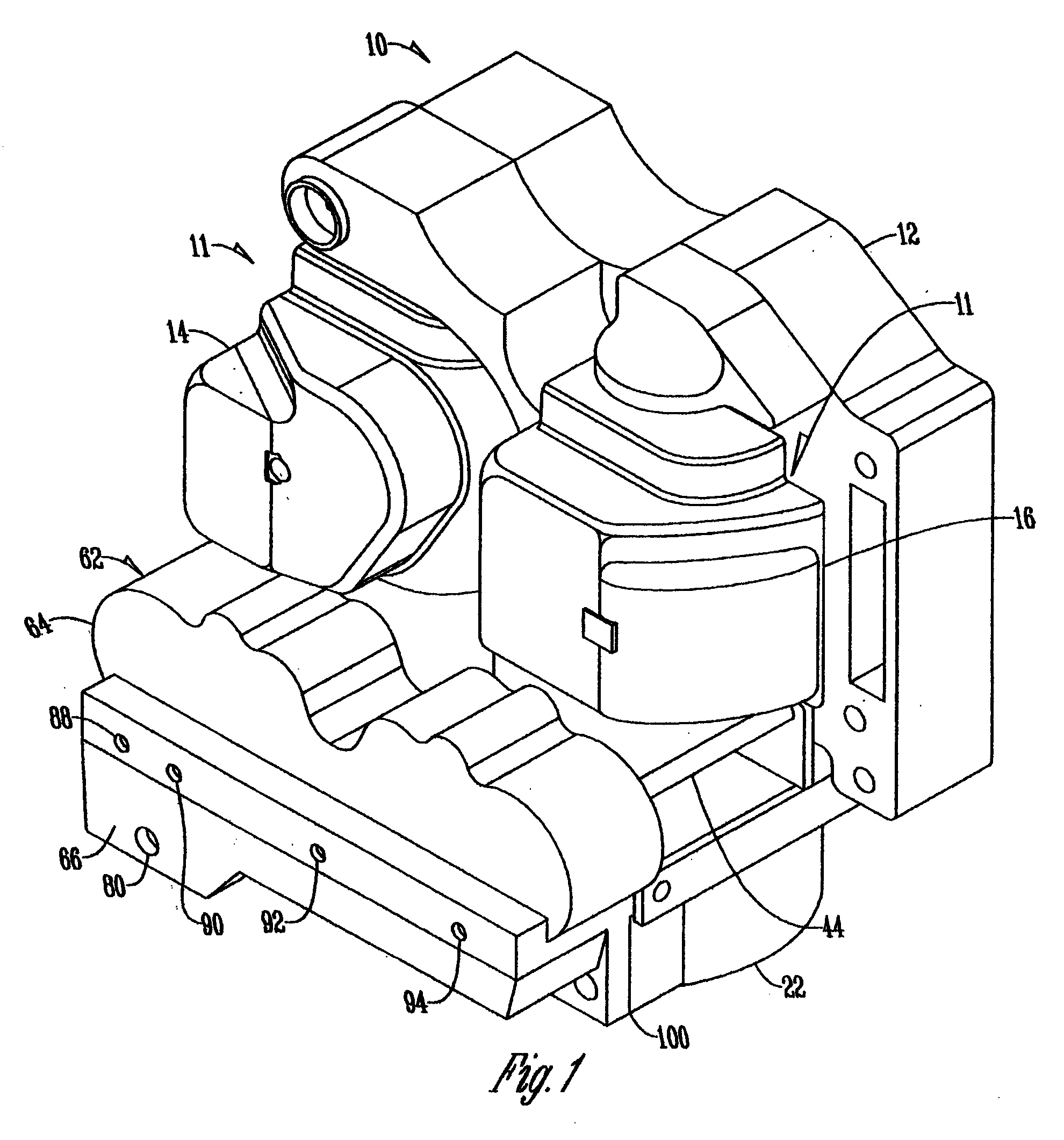
[0034] Referring to FIG. 1, the hydrostatic module 10 of the present invention includes bent axis hydrostatic units 11 and a frame 12. The frame 12 acts as a structural unit to hold and locate other components, and also reacts against forces within module to hold components in place.

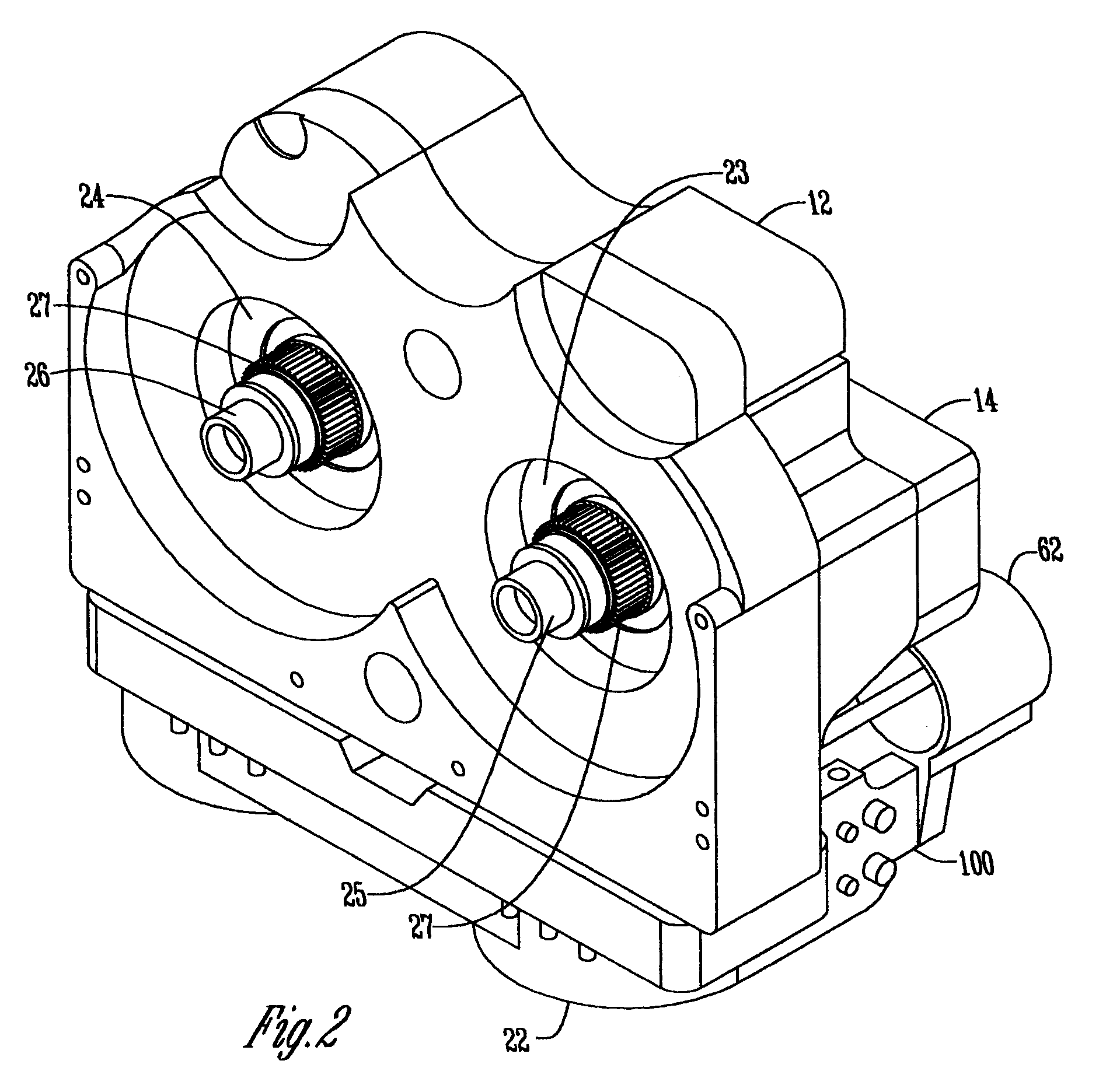
[0035] Referring to FIG. 4, a clutch unit yoke 14 and ring unit yoke 16 contain and carry hydrostatic power units (cylinder blocks or kits) 23 and 24, respectively, and are pivotally mounted on the frame 12 to pivot with respect to the frame 12 in intersecting paths. The two yokes 14 and 16 are captured between the frame 12 and a manifold 22, when assembled.

[0036] The hydrostatic power units 23 and 24 are operatively connected to a pair of parallel laterally spaced shafts 25 and 26, respectively. The shafts 25 and 26 are rotatably supported by the frame 12 and directed outwardly from the frame 12 in the same direction. The hydrostatic power units 23 and 24 operate to rotate the shafts 25 and 26.

[0037]...


PUM


Abstract

A hydrostatic module is disclosed, including a pair of shafts rotatably supported by a frame. Two yokes are pivotally mounted on the frame, each having complimentary surfaces to the other yoke and to the frame, minimizing the space occupied by the yokes. Stop means are provided on the yokes and on the frame to limit the pivotal movement of the yokes. A hydrostatic power unit is carried by each yoke, each connected to one of the shafts. A control system, having a single piece control housing containing servo pistons, pivots the yokes. The servo pistons independently determine the orientation of the yokes. A single piece fluid control porting plate is secured to the control housing to route hydraulic fluid to multiple locations within the control housing. A fluid manifold serves as a main structural element, with intimate proximity between the manifold and the control housing allowing simplified fluid exchange therebetween.

Description

CROSS REFERENCE TO A RELATED APPLICATION [0001] This application claims the benefit of Applicants' Provisional Application Ser. No. 60 / 482,932 filed Jun. 27, 2003.BACKGROUND OF THE INVENTION [0002] The present invention relates to the field of variable displacement bent axis hydraulic units. Bent axis hydraulic units have been known for many years. [0003] Such devices have power output limited to their physical size. When additional power is required, a solution is to provide a unit of larger size. However, space and size become a problem in certain vehicle designs and serve to prevent larger bent axis hydraulic units from accommodating this situation when more power and limited space are specified. [0004] It is therefore a principal object of this invention to provide a bent axis hydrostatic module with multiple yokes which are shaped and positioned to nest with each other so as to minimize the space requirement of the entire unit. [0005] It is a further object of this invention to...

Claims


Application Information

Patent Timeline
IPC IPC(8): B60K17/356F03C1/06F04B1/24F04B23/06F04B53/00
CPCF03C1/0639F16H2039/005F04B1/24
Inventor FLEMING, JOHNMEYER, SCOTTKARDELL, DOUGMASINI, CHRISTOPHER P.
Owner DANFOSS POWER SOLUTIONS INC
Why Eureka
Try Eureka