Magnetized torque transducer elements

a transducer element and magnetized torque technology, applied in the field of torque or force sensor, can solve the problems of noise masked output at or around the zero region, and zero output at zero torqu

Inactive Publication Date: 2005-06-28
ABAS
View PDF14 Cites 52 Cited by
  • Summary
  • Abstract
  • Description
  • Claims
  • Application Information

AI Technical Summary

Problems solved by technology

The problem posed to some users of magnetoelastic torque transducer elements of the circumferential magnetic field kind discussed above is that at zero torque in the shaft, the magnetic field output from the transducer element is zero.
Outputs at or around the zero region are liable to be masked by noise.
Another related problem with circ...

Method used


Image

  • Magnetized torque transducer elements
  • Magnetized torque transducer elements
  • Magnetized torque transducer elements

Examples


Embodiment Construction

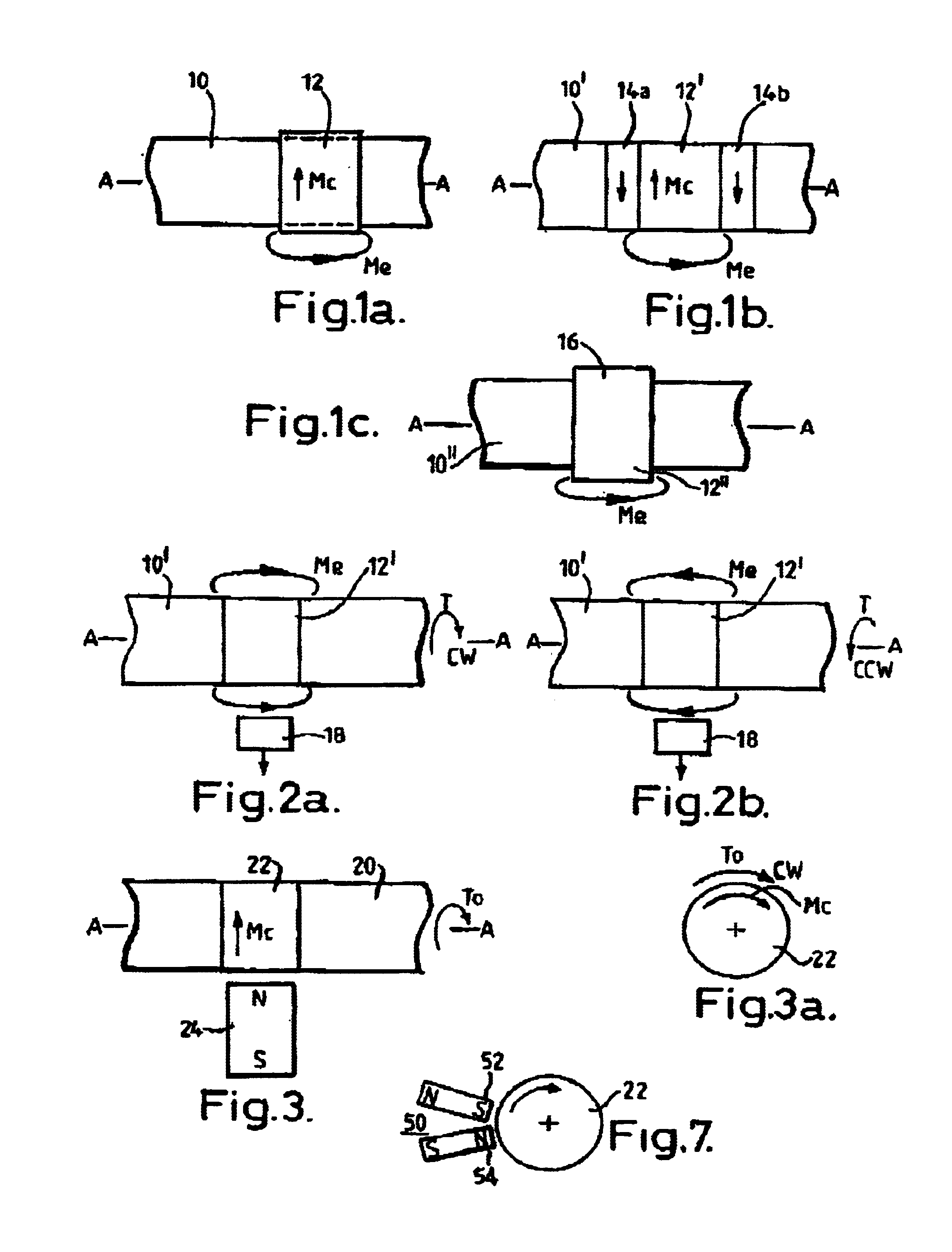
[0033]Referring to FIG. 3, a solid shaft 20 of the kind shown in FIG. 1b is seen being subject to magnetisation Mc at a portion 22 while under a predetermined torque To. The magnetising method may use a permanent magnet 24 brought up adjacent to the portion 22 of shaft 20 while it is rotating under the predetermined torque To. A preferred arrangement is shown in FIG. 7. Instead of a permanent magnet, an electromagnet may be used or the shaft subjected to an axially directed current. Various methods are available and some of these are disclosed in the above three U.S. patents and particularly U.S. Pat. No. 5,520,059; and also in above-mentioned PCT publication WO99 / 56099. Alternatively the shaft may be held static with the predetermined torque To applied to it while a magnet system is moved around it. Magnetisation by an axially directed current is also applicable to the static case.

[0034]FIG. 3a indicates the directions of pre-torque To and circumferential magnetisation Mc about the...


PUM


Abstract

The problem of magnetoelastic cirumferentially-magnetized torque transducers having a zero output magnetic field at zero torque is solved by pre-torqueing. This entails is circumferentially magnetizing the transducer element at a predetermined torque. The technique is advantageously applied to a pair of transducer elements (32, 34: 62, 64) whose outputs are combined (FIG. 6a: 76) to provide a range of measurement of torque (clockwise and counterclockwise) including zero torque. Various combinations of direction of pre-torque and direction of circumferential-magnetization are discussed. A circuit (FIG. 8) is disclosed for combining the signals to obtain a reference level (84) for gain control of the combined output signals V o from the two transducer elements (60, 62). Also disclosed is the application of the invention to other forms of torque transducer element in which a magnetic field is stored. One form is longitudinal magnetization (FIG. 10a). Another is radially spaced magnetization (FIG. 12a: FIG. 13).

Description

FIELD OF THE INVENTION[0001]This invention relates to a torque or force sensor based on a magnetised transducer element, to a magnetised transducer element and to a method of forming such an element. The invention also relates to a shaft assembly including plural transducer elements and to a torque sensor system incorporating such a shaft assembly.[0002]The invention will be particularly described in relation to transducer elements which are of magnetoelastic material and which are circumferentially magnetised, that is are of an annular form, e.g. circular form, which is magnetised in a closed loop around the annulus. The prior art transducer elements of this type provide a zero output at zero applied torque which can present a problem in practical applications as will be explained below. However, the invention has wider application to other magnetic-based transducer elements which need not necessarily utilise the phenomenon of magnetoelasticity in generating a torque-dependent or f...

Claims


Application Information

Patent Timeline
IPC IPC(8): G01L3/10G01L1/12
CPCG01L3/102
Inventor MAY, LUTZ AXEL
Owner ABAS
Why Eureka
Try Eureka