Exhaust pipe, and method of making an exhaust pipe

a technology of exhaust pipe and pipe body, applied in the direction of flexible pipes, rigid pipes, adjustable joints, etc., can solve the problems of exhaust pipe between two fixed attachment points, e.g., a problem, etc., and achieve the effect of convenient interconnection of ends, precise parting cuts, and advantageous application

Inactive Publication Date: 2005-06-28
BENTELER AUTOMOBILTECHNIK GMBH
View PDF18 Cites 22 Cited by
  • Summary
  • Abstract
  • Description
  • Claims
  • Application Information

AI Technical Summary

Benefits of technology

[0010]Since the end portion of the inner pipe of the first length portion engages between both end pieces of the outer pipes, an effective and reliable positioning of the end portion of the inner pipe is realized.
[0013]According to another feature of the present invention, the adjacent ends of the first and second length portions may be connected to one another in a fluid-tight manner. The end pieces of the outer pipes may be placed in immediate abutting relationship with the end portions of the inner pipes. This, of course, is not necessarily required because it is also possible to provide an indirect contact between these components via interposed sealing parts which prevent an escape of exhaust gases from the exhaust pipe.
[0014]According to another feature of the present invention, there may be provided an encapsulating member for encasing the overlapping end pieces of the outer pipes of the first and second length portions in a fluid-tight manner to thereby compensate relative movements between the end pieces. Compared to the incorporation of sealing parts within the sliding fit, the application of a fluid-tight encapsulation by using a separate encapsulating member has an advantage because the sliding fit can be configured simpler. The placement of the encapsulating member upon the outer pipes to compensate relative movements results in a functional separation in the area of the sliding fit. The fluid-tight encapsulation is realized by the separate encapsulating member while the compensation of the relative movement is effected by a triple sliding fit.
[0015]The use of a bellows is suitable for compensating relative movements while at the same time realizing the fluid-tight encapsulation of the exhaust pipe. Depending on the required service life, the bellows may basically be a replacement part of the exhaust pipe. The geometry of the bellows can easily be modified, for example through changing the number of folds.
[0022]According to another feature of the present invention, the adjacent ends are deburred before the joining step. Deburring facilitates an interconnection of the ends to form a sliding fit, especially in the presence of narrow tolerances.
[0023]The method according to the present invention can be advantageously applied when the outer pipe and the inner pipe adjoin one another in the area of the adjacent ends. The flat engagement of the inner pipe with the outer pipe in the area of the adjacent ends results in a secure placement of the inner pipe so that precise parting cuts are possible. The use of, e.g., mandrels placed in the inner pipe, to realize an added positional fixation of the inner pipe before the parting cut is not required. In particular, when the outer diameter of one end of the adjacent ends is smaller than the inner diameter of the other one of the adjacent ends, the end with smaller diameter can easily be inserted into the other end. Suitably, the ends are configured in their diameter in such a way that a clearance fit between the outer diameter of the end positioned inwardly and the inner diameter of the end position outwardly is established, so that a sliding fit between the individual length portions of the exhaust pipe is provided to compensate relative movements of the outer pipes and the inner pipes.

Problems solved by technology

The attachment of the exhaust pipe between two fixed attachment points, e.g., an exhaust manifold and an exhaust turbocharger, poses, however, a problem.
In addition, the rapid temperature increase in an exhaust pipe results in a temperature drop between the inner pipe and the outer pipe so that additional relative movements between inner and outer pipes have to be compensated.

Method used


Image

  • Exhaust pipe, and method of making an exhaust pipe
  • Exhaust pipe, and method of making an exhaust pipe
  • Exhaust pipe, and method of making an exhaust pipe

Examples


Embodiment Construction

[0027]It will be appreciated by persons skilled in the art that the depicted embodiment is to be understood as illustrative of the invention and not as limiting in any way.

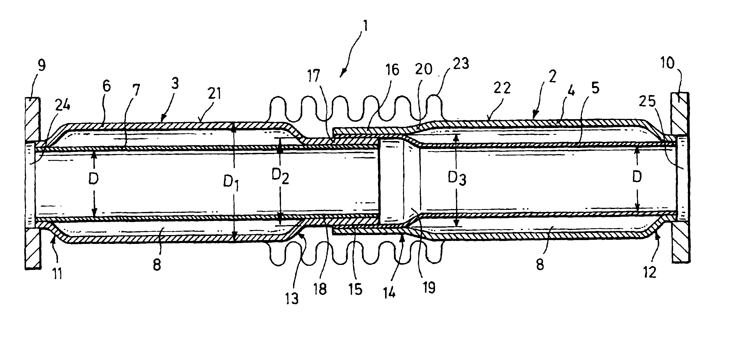
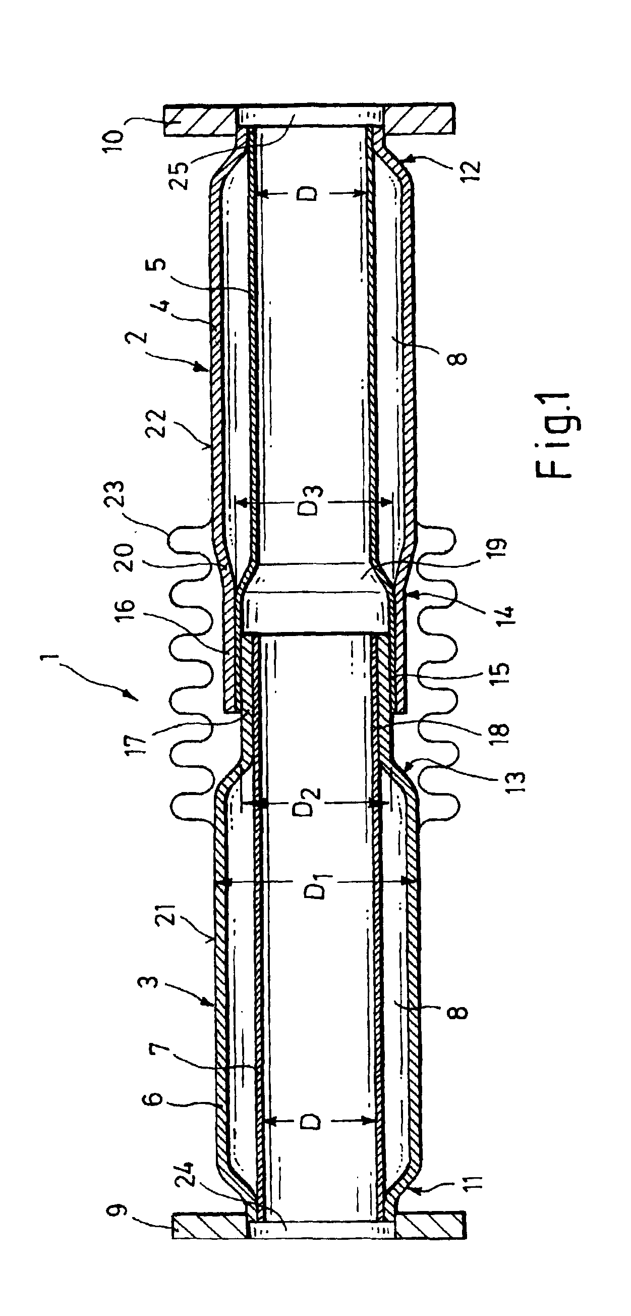
[0028]Turning now to the drawing, and in particular to FIG. 1, there is shown a longitudinal section of a double-walled exhaust pipe according to the present invention, generally designated by reference 1 and including a first length portion 2 and a second length portion 3. The exhaust pipe 1 is configured as double-walled pipe with a first outer pipe 4 and a first inner pipe 5 in the first length portion 2, and a second outer pipe 6 and a second inner pipe 7 in the second length portion 3. The outer pipes 4, 6 and the inner pipes 5, 7 are disposed in concentrate relationship, with an annular gap 8 being defined between the outer pipes 4, 6 and the inner pipes 5, 7. Although the exhaust pipe 1 is substantially straight in the non-limiting example of FIG. 1, it is, of course, also possible to configure the exhaust ...


PUM


Abstract

An exhaust pipe includes first and second length portions, each having an outer pipe and an inner pipe positioned relative to one another to define an annular gap therebetween. The length portions are placed in confronting disposition with their adjacent first ends interconnected for relative movement in a longitudinal direction. An end piece of the outer pipe of the first length portion is disposed in surrounding relationship to an end piece of the outer pipe of the second length portion at interposition of an end portion of the inner pipe of the first length portion, wherein the end pieces of the outer pipes of the first and second length portions and the end portion of the inner pipe of the first length portion are positioned for relative movement in the longitudinal direction, so as to define a triple sliding fit.

Description

CROSS-REFERENCES TO RELATED APPLICATIONS[0001]This application claims the priority of German Patent Application, Serial No. 101 57 131.3, filed Nov. 21, 2001, pursuant to 35 U.S.C. 119(a)-(d).BACKGROUND OF THE INVENTION[0002]The present invention relates to an exhaust pipe, and to a method of making an exhaust pipe.[0003]Internal combustion engines are generally equipped heretofore with a three-way catalytic converter for emission control. Three-way catalytic converters require a particular starting temperature to assume the actual emission control function. Regulatory exhaust standards demand an increasingly shorter time period for the catalytic converter to reach the starting temperature, the so-called “light of time”, whereby an operating temperature of >350° C. should be reached in shortest possible time.[0004]The use of air gap insulated exhaust pipes between the cylinder outlet and the catalytic converter is one approach to conform to these standards. Air gap insulated exha...

Claims


Application Information

Patent Timeline
Patent Type & Authority Patents(United States)
IPC IPC(8): F01N7/14F01N7/18F01N13/08F01N13/18F01N13/14F16L27/12
CPCF01N13/08F16L27/12F01N13/18F01N13/14
Inventor GABRIEL, HEINRICHBOLTE, ALBRECHTHUMBURG, ERHARDTSMATLOCH, CHRISTIANKLEINSCHMIDT, JURGEN
Owner BENTELER AUTOMOBILTECHNIK GMBH
Why Eureka
Try Eureka