Multi-section conveyor drive roller

Active Publication Date: 2005-06-28
DORNER MFG. CORP.
View PDF8 Cites 34 Cited by
  • Summary
  • Abstract
  • Description
  • Claims
  • Application Information

AI Technical Summary

Benefits of technology

[0006]It is one object of the present invention to provide a conveyor roller construction which maintains the drive traction on the belt and supports belt tracking without requiring machining of the external surface of the roller.
[0008]It is a further object of the present invention to provide a segmented conveyor roller construction which is easy to assemble / disassemble and cost effective to produce.

Problems solved by technology

Although the center drive unit illustrated in the '447 patent is efficient for driving the conveyor belt, threading the conveyor belt through the center drive unit is a tedious and time consuming task.
Further, the multiple rollers require additional parts and manufacturing costs, such as for machining of the outer walls of the various rollers.
Because some drive rollers may be four feet in length and six inches in diameter, such machining can be labor intensive and costly.

Method used


Image

  • Multi-section conveyor drive roller
  • Multi-section conveyor drive roller
  • Multi-section conveyor drive roller

Examples


Embodiment Construction

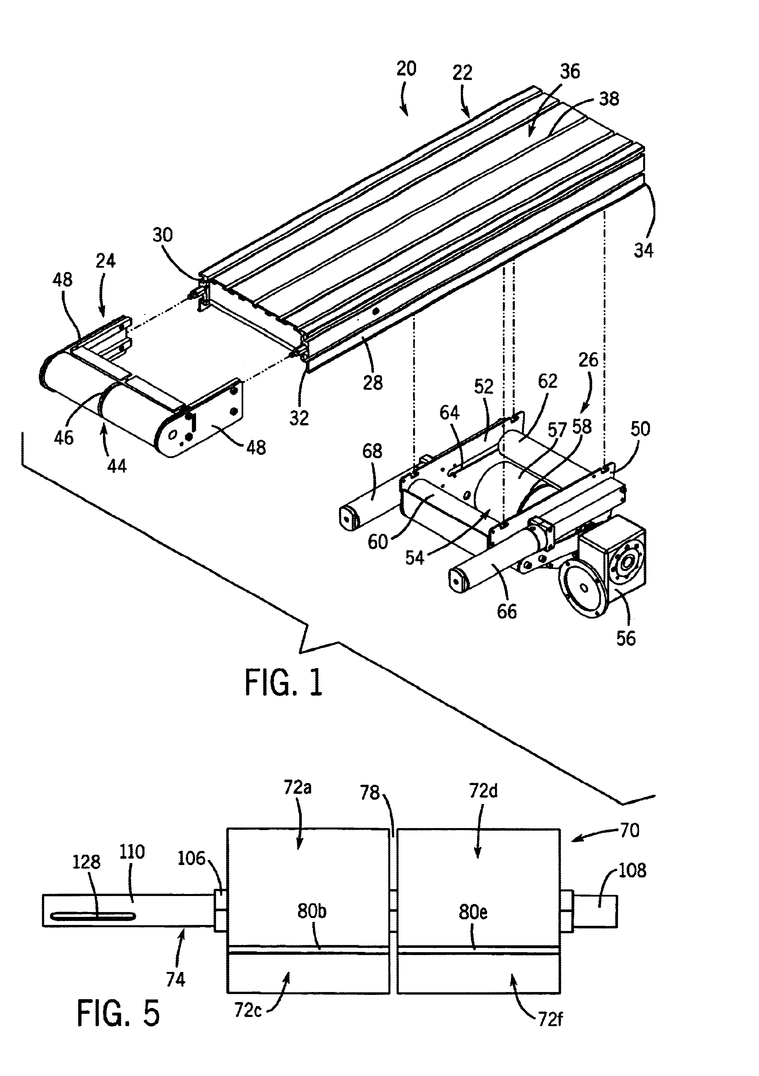
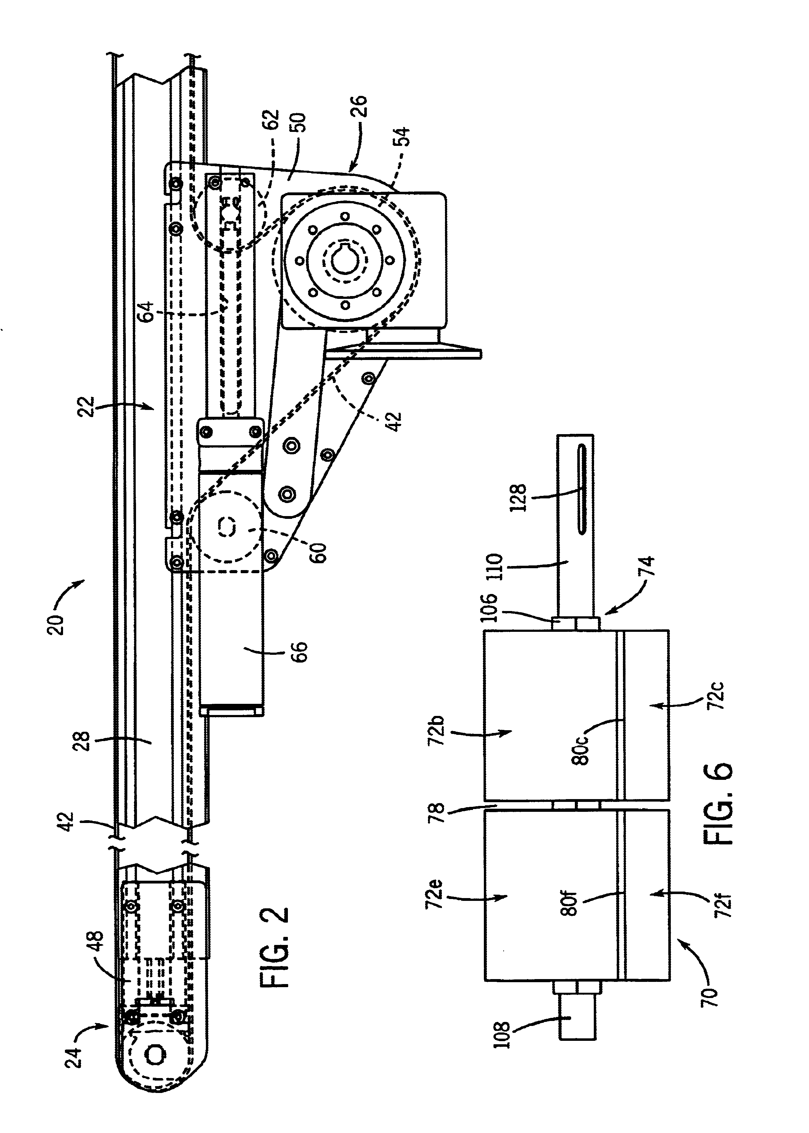
[0023]FIG. 1 illustrates a conveyor assembly 20 including a conveyor frame assembly 22, a tensioning section 24 and a center drive unit 26 as generally set forth in copending U.S. patent application Ser. No. 10 / 385,906 filed Mar. 11, 2003, the disclosure of which is herein incorporated by reference.

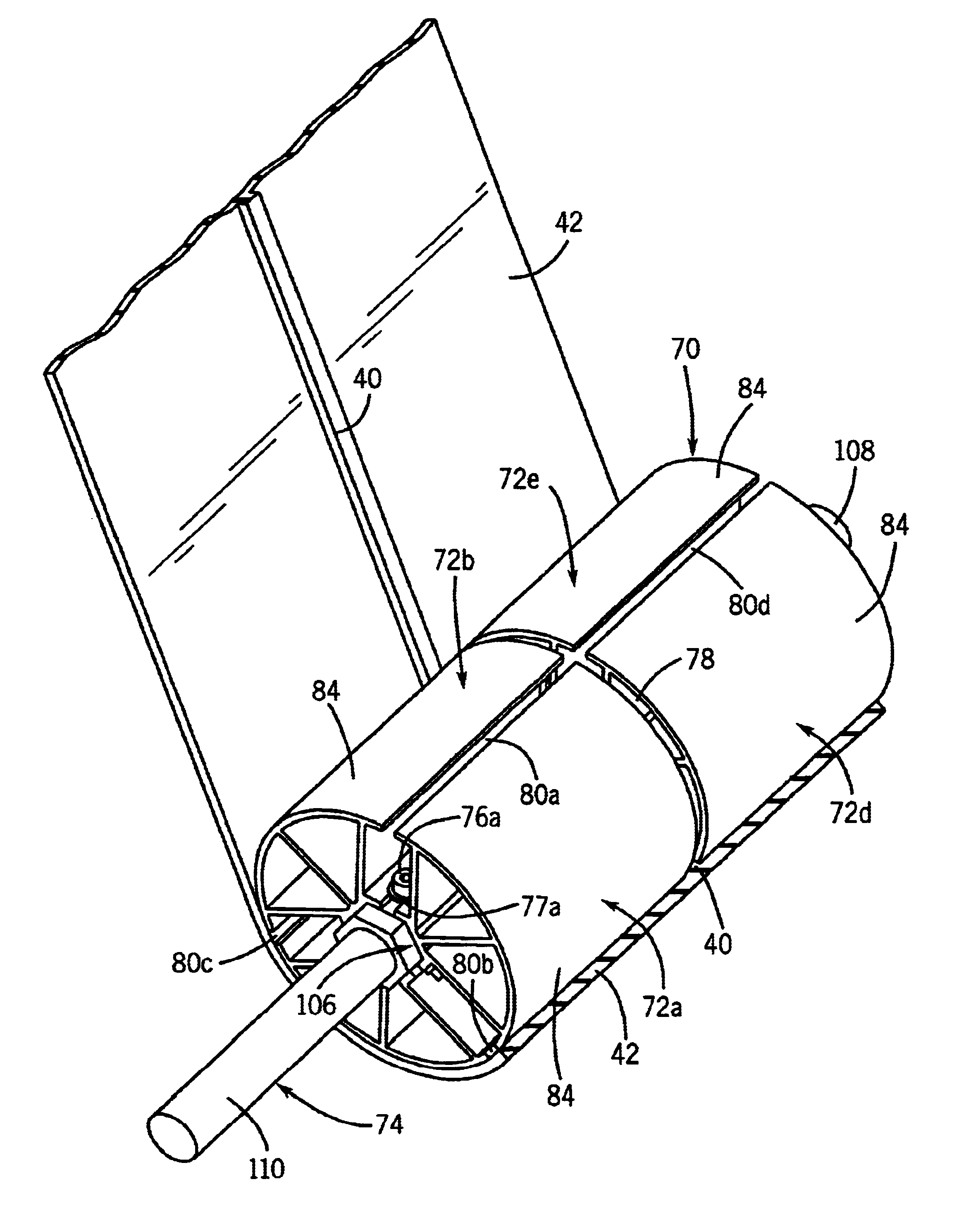
[0024]The conveyor frame assembly 22 includes a pair of side frame members 28, 30 that each extend between a first end 32 and a second end 34. The side frame members 28, 30 are spanned by a center bed plate assembly 36 having a center groove 38 that receives a centrally located rib 40 formed on the inner surface of an endless conveyor belt 42 as shown in FIG. 4. The center groove 38 aids and provides the proper tracking of the moving conveyor belt 42 along the conveyor frame assembly 22. The tensioning unit 24 is attached to the first end of the conveyor frame assembly 22 and includes a single idler roller 44 having a center groove 46 for receiving the rib 40 formed on the inner surface o...


PUM

PropertyMeasurementUnit
Angleaaaaaaaaaa

Abstract

A multi-section conveyor roller is engageable with a conveyor belt moveably mounted on a conveyor frame assembly. The roller includes a rotatable mounting hub connected to the conveyor frame assembly, and a plurality of adjacently disposed roller segments fixed to the mounting hub to form belt-engaging, curved outer wall surfaces. The outer wall surfaces are separated by a number of gaps, at least one of the gaps receiving rib structure provided on the conveyor belt for maintaining proper movement of the conveyor belt on the conveyor frame assembly.

Description

FIELD OF THE INVENTION[0001]The present invention relates generally to endless belt conveyors. More particularly, the present invention pertains to an endless belt conveyor utilizing a roller construction which maintains belt tracking and drive traction with the belt without requiring machining of the peripheral wall of the roller.BACKGROUND OF THE INVENTION[0002]Typically, the endless belt of a conveyor is driven either by an end drive unit positioned to drive a spindle or roller located at either end of a conveyor frame, or by a center drive unit positioned along the length of the conveyor frame and mounted beneath the conveyor frame. In a center drive unit, the continuous belt is wound through a series of rollers, including a drive roller and a tensioning roller, to impart the required force to the conveyor belt. One such center drive unit is illustrated in Ewert U.S. Pat. No. 5,203,447, the disclosure which is hereby incorporated by reference. As can be understood in the Ewert p...

Claims


Application Information

Patent Timeline
IPC IPC(8): B65G23/00B65G23/04B65G39/00B65G23/44B65G39/02
CPCB65G21/105B65G23/04B21C23/145B65G39/02B65G23/44
Inventor ERTEL, DANIEL E.
Owner DORNER MFG. CORP.
Why Eureka
Try Eureka